
 中国
中国 马来西亚
马来西亚  韩国
韩国  美国
美国  加拿大
加拿大  英国
英国  德国
德国  墨西哥
墨西哥  巴西
巴西  捷克共和国
捷克共和国  法国
法国  西班牙
西班牙 如何正确地安装轴和轮毂组件
作者
下载白皮书
卷制弹性圆柱销
使用卷制弹性圆柱销在轴上安装轮毂或齿轮的主要好处之一在于卷制圆柱销能够防止
小孔损坏。另一个好处是,卷制圆柱销能承受的孔径公差更大,胜过其他任何压接销。这就降低了组件的总生产成本。
为了获得铰接系统的最大强度并防止组件遭到损坏,必须遵守以下几条设计原则
设计原则可以分为两组:1) 轴和轮毂 2) 销。
1. 轴和轮毂注意事项
- 轴上的孔径不得超过轴直径的三分之一。对于低碳钢和有色金属的轴,建议使用标准载荷销。重型载荷销的额外强度只有在孔径小于轴直径的四分之一或轴硬化时才有帮助(图 1)。
- 建议将轮毂的最小壁厚设计为销直径的 1.5 倍。否则,轮毂的强度无法抵挡销的剪切强度(图 1)。.随着轮毂壁厚增加,销周围的材料面积也会增加。
- 穿过轴和轮毂的孔径应该严格匹配,以防止销在孔内移动。建议轮毂与轴之间的孔径差距不超过 0.05mm(0.002 英寸)以免相互之间的零件移动。否则,销会受动态载荷影响,这样一来速度的微弱变化也会引起冲击组件的力发生很大变化
- 小孔应位于轴和轮毂的中心,以免压力集中,同时确保销周围有足够的材料承受施加的力。
- 如果小孔无法严格匹配,建议分散轴与轮毂之间的孔径公差。将公差中较长的一段用于最大接合长度的组件,较短的一段用于其他组件。

图1
A:轮毂的最小壁厚为销 直径的 1.5 倍B: 孔径不得超过 轴直径的 1/3

齿轮轴中的卷制圆柱销

图2

图3
A:两点接触B:销插入时出现剥皮
C完全圆周接触
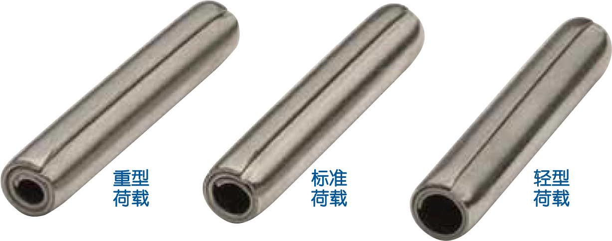
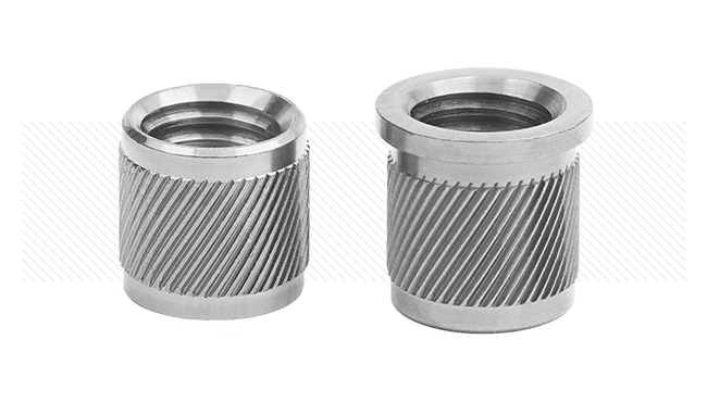
SPIROL® 卷制弹性圆柱销有三种载荷类型, 可提供最佳强度和灵活性。
- • 不建议在小孔上使用埋头孔。此外,设计轴的外直径 (OD) 和轴环的内直径 (ID) 时,应确保剪切面 (ODID) 间的距离不超过 0.13mm(0.005 英寸)。因为在两种情况下,施加扭矩的区域内会形成销的跨距。这可能引起弯矩,缩短销的使用寿命(图 2)。.
• 在柱状体表面的小孔内插入圆柱销,就会在销和小孔之间形成两点接触。这样压力就只会集中在外围的两点上。
- 为了增加小孔外围和销之间的接触面积并简化安装过程,应在小孔的外表面提供一个平面(图 3).
2. Coiled Pin Considerations
- 务必从销将经受的载荷开始考虑。然后评估主体材料以判断 载荷类型的卷制圆柱销. 然后根据SPIROL®卷制弹性圆柱销设计指南/产品目录中的剪切强度表来判断传输适当载荷类型中载荷所需的销直径,同时需进一步考虑以下原则:
- 只要空间允许,就用标准载荷 销。 标准载荷卷制弹性圆柱销完美融合了强度和灵活性,可用于有色金属和低碳钢组件。同样建议用于重型组件,因为标准载荷销具有更强的减震能力。
- 重型载荷销,在空间或设计限制不允许使用直径较大的标准载荷卷制圆柱销时,硬化材料只应使用重型载荷销。这条规则有一个例外,即奥氏体(镍)不锈钢圆柱销不得用于重型组件。
- 轻型载荷销用于柔软、脆性或薄型材料或者小孔靠近边缘的情况。在不受重大载荷限制的情况下,因为需要的插入力较小,所以常常使用轻型载荷销。
虽然本文提供了一般的设计原则,但建议咨询紧固和连接方面的 专业应用工程师, 以确保采用各
种应用领域内最优的铰链设计。