
 中国
中国 马来西亚
马来西亚  韩国
韩国  美国
美国  加拿大
加拿大  英国
英国  德国
德国  墨西哥
墨西哥  巴西
巴西  捷克共和国
捷克共和国  法国
法国  西班牙
西班牙 如何设计使用卷制弹性销定位的装配
作者
下载白皮书使用卷制圆柱销时,为了实现最佳定位,需要遵循两个主要设计因素:
- 1) 主体上和配对构件上的孔的直径必须尺寸合适以实现预期的干涉和精确定位。
- 在所有应用中,提供主要保持力的构件中的卷制弹性圆柱销的接合长度必须不低于该销总长度的 60%。剩余突出长度和配对构件匹配。 对通孔的应用建议增加接合的初始长度;但是,卷制弹性圆柱销还是需要突出以对准配对构件。 (图1)
最大对准精度的干涉配合:
卷制弹性圆柱销是功能弹簧,可贴合其所安装的孔。 要实现校准的最大精度,装配力不应超过“轻”按以安装配对构件的力。 因卷制弹性圆柱销的载荷类型、定位销的数量和主体材料而异,这可能只需用手掌或木锤轻轻一击。 Solid Dowel 。干涉配合不能与通常需要气动压机或液压机装置的传统的固定销混淆。这是卷制弹性圆柱销的一个主要优势。
为了确保轻压配合,理想情况下,主体上和配对构件上孔的尺寸应在推荐公差范围内精确匹配。如果孔不是作为一个组件时一起钻的,就可能不实用了。
在孔不能精确匹配或珩磨/扩孔成本过高的情况下,卷制弹性圆柱销的显著优点是它能够弥补偏大的孔公差。建议的公差范围可按如下所示在构件间进行划分图2.
(说明:越少利用允许的制造公差可进一步提高组件的匹配和对准。)
用于进程对准和易于装配的间隙配合:
如果销上的间隙配合旨在便于装配,则有必要在销的自由端补偿弹簧恢复。为确定销的自由端的最大直径,将该销长度的 60% 装配至主保持主体的最大孔尺寸中,并测量露出部分的直径。根据预期的对齐精度,应在该销的自由端添加 0.025 mm (0.001”) 到 0.05 mm (0.002”) 的空隙。(图 3)
当用作无配合定位销时,不需要考虑装配力;但是,要注意,将卷制弹性圆柱销用作干扰配合方案时应予以考虑。正如上文所述,卷制弹性圆柱销具备可提供零间隙配合的优势,而且不会增加高插入力的复杂性。

图1
该图展示了合适的装配深度。当卷制弹性圆柱销的装配深度小于其总长度的 60%,将出现以下两种情况:
- (y) 或自由端的直径将无法得到适当地控制,继而在生产过程中部件与下游配合时导致“配合”不一致。
- 在后续拆卸过程中,销可能无法保持在构件内其本应该定位的位置上。在构件之间使用了多个定位销的情况下,这一点尤其重要。

图2
为CLDP4x20LBK干涉配合的推荐的孔尺寸与销深度
为定位选择合适的载荷类型:
卷制弹性圆柱销有三种“载荷”,使设计者能选择强度、弹性与直径的最佳组合满足不同主体材料与应用需求。推荐在软性材料(铝,塑料),脆性材料(陶瓷)或薄型材料以及材料上的孔接近边缘的这些情况下使用轻型载荷圆柱销。 大部分定位应用中,圆柱销并非通常受制于重型载荷。由于插入力较低,安装变得简单, 在这些情况下通常使用轻型载荷圆柱销。标准载荷圆柱销主要设计用于无铁材料和软钢组件中。 重型载荷圆柱销 应仅限用于硬化材料中,且该材料中的空间和设计限制排斥较大直径的标准型载荷圆柱销。
虽然该文章分享了通用的设计指南,还是推荐咨询专注紧固与连接件研究的 应用工程师 ,确保设计出合适的零部件,为
每个具体装配选择合适的卷制弹性圆柱销。
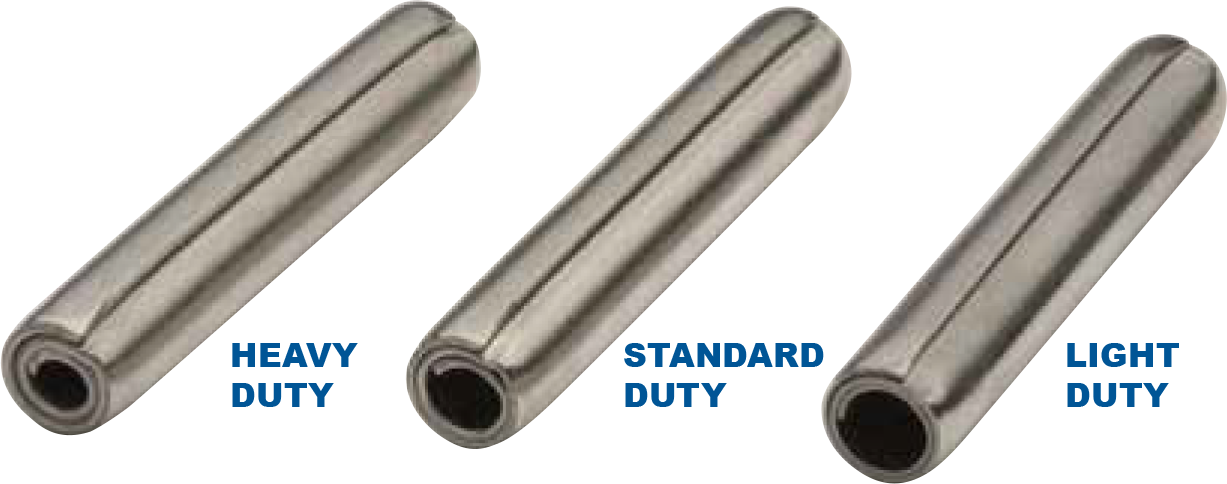
卷制弹性圆柱销常被用于定位。有重型、标准型和轻型三种载荷满足不同主体材料与应用需求。