
 中国
中国 马来西亚
马来西亚  韩国
韩国  美国
美国  加拿大
加拿大  英国
英国  德国
德国  墨西哥
墨西哥  巴西
巴西  捷克共和国
捷克共和国  法国
法国  西班牙
西班牙 间隙对卷制弹性圆柱销剪切属性的影响
作者
下载白皮书卷制弹性圆柱销用途极为广泛,是众多市场中离不开的紧固件。SPIROL 通过对众多应用的评估发现了导致销连接强度降低的常见设计/制造错误。这些问题中包括但不限于埋头孔、沉头孔和配合件之间的间隙,这些情况会产生间隙,导致销弯曲从而降低销的有效剪切强度。
卷制弹性圆柱销的剪切强度是适用行业规范规定的最小剪切强度值的两倍。由于卷制弹性圆柱销具有动态性,因此其剪切值是通过测试而非传统计算方式获得的。测试条件采用 ASME B18.8.2、ASME B18.8.3M、ISO 8749 等标准规定的规格。量具采用硬化钢,在剪切平面中的最小间隙为 0.005”(0.13mm)。这种测试条件非常理想,可确保销处于剪切力作用之下。随着装配件中间隙大小与测试参数之间的差异加大,销会因弯曲(不是剪切力)而失效,并且强度开始下降。应了解超过理想剪切条件多少会影响销连接的性能,这一点非常重要,因为这可能影响装配件的完整性和使用寿命。
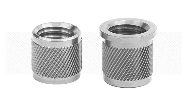
为使销从一个孔进入另一个孔,在连接元件之间要打上埋头孔或沉头孔。尽管这样做的目的是可以理解的,但是产生的间隙通常是不可接受的。SPIROL 的卷制弹性圆柱销采用深度倒角处理,更便于在安装时对准孔心,因此不需要使用埋头孔或沉头孔。(图 1)。 尽管这些特点容易被忽视,但是却造成间隙和弯曲,使销在承受剪切力时性能下降。强度变差进而导致疲劳,使销过早失效。尽管造成失效的原因不难发现,但是如何量化对过早失效的影响非常重要。
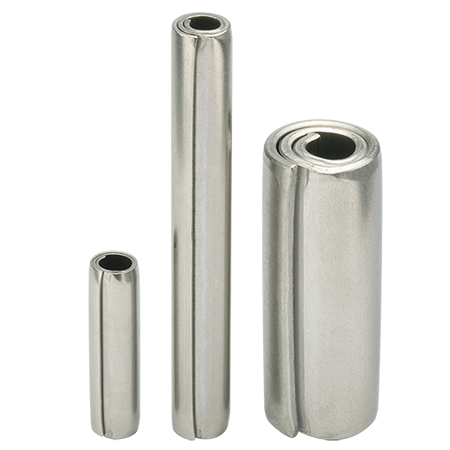
SPIROL 轻型卷制圆柱销测试选用 ,为了更好地了解性能变化情况,采用逐步增加剪切面间隙的做法。之所以选择轻型销是因为这种销容易安装和拆卸。选择的销为标准型 CLDP 0.250 x 2.500LBK((或轻型高碳钢卷制圆柱销,表面涂防锈油(触摸干燥))。这种销具有足够的长度,可以在不同间隙下进行测试。

轻型卷制圆柱销
卷制圆柱销在安装时无需借助沉头孔或埋头孔。平滑且同心度较好的倒角具有平整,无毛刺的两端,可实现无故障装配。

图 1
A:沉头孔间隙
B:埋头孔间隙
Instron Model 3384 使用标准的 ASME B18.8.2剪力块(图 2)对销进行测试。使用平均厚度分别为 0.072”(1.83mm) 和 0.120”(3.05mm) 的两种不同尺寸的垫圈增加间距,剪力块冲头位于支撑夹具的中间位置。如前面所述,为避免销发生弯曲,剪切面之间的最大间隙应为0.005”(0.13mm)。
|
|
 图 3B: 图 3B:因弯曲而发生破坏的卷制圆柱销的外层发生变形,并在多个剪切面上发生断裂 |
 图 3A:
图 3A:可以观察到,因弯曲(而不是剪切力)而失效的销的外观差异很大。如图 3A 所示,因剪切力而失效的销在一个平面上出现断裂。尽管卷层发生变形,但是它们看起来是平的,并且外层倒向一个方向。 图 3B 所示为在 0.120”(3.05mm) 间隙下测试后的销。在该图中,通过弯曲部位很明显可以看出发生了弯曲,进而导致表面断裂。
此外,表面断裂不是发生在一个平面上,而是每个卷层表现出不同程度的断裂。同时检查失效销的断裂面及安装销的实际主体。主体元件不按图纸设计而导致间隙的情况并不少见。只有在对应用中使用的所有元件进行检查后方能准确地确定根本原因。
30 块在不同条件下进行测试的样品的测试结果。表 1 列出.测试数据与间隙越大发生断裂的最大作用力越小的理论相符。一个有趣的现象是 0.072”(1.83mm) 和 0.120”(3.05mm) 之间的作用力变化较小。当间隙从 0.005”(0.13mm) 增加到0.072”(1.83mm) 时,销的断裂作用力下降 18% 或约 800 lbs (3.6 kN),但是继续将间隙增加到0.120”(3.05mm) 时,作用力又继续降低约 150 lbs (0.7kN),总计变化 22%。

图 2:
ASME B18.8.2 标准使用的典型销剪力试验夹具
A: 硬化衬套
B:载荷
C: 剪切块
D: 垫片
E:卷制销
F:带帽螺钉
G:支撑夹具
H:剪切块的垫片&导向装置
| .0.005″ 间隙(剪力) | .0.072″ 间隙 | .0.120″ 间隙 | |
| 平均值 | 4,257.64 | 3,475.44 | 3,312.54 |
| 最小值 | 4,029.39 | 3,340.20 | 3,211.69 |
| 最大值 | 4,548.73 | 3,583.60 | 3,395.75 |
| 标准偏差 | 125.77 | 56.21 | 45.94 |
表 1
30 个 CLDP .250 x 2.500 LBK 测试样品的失效力(lbs.)数据汇总
这种现象可以用一般的材料原理来解释。在评估应力-应变特性时,弯曲强度通常用来描述较脆的陶瓷材料,但是它定义为由于弯曲力作用而发生断裂时的应力。该特
性通过三点或四点弯曲试验进行测试,它采用横向弯曲测试的方法,施加一个或两个载荷,并在预定的间距 (L)处放置底部支撑。弯曲试验模型采用一个销和一个剪力块的简化形式。
弯曲应力方程为1:
其中Ff 是断裂载荷,R 是销的半径,L 是支撑点间距。随着间隙对称地的增加,支撑点间距随之增加, L变成L+2g其中 g是一侧增加的间隙距离。图 4 是利用已知值绘制的 g 对作用力的影响
关系图。当间隙超过推荐最大值0.005″ (0.13mm) 时,剪切变形变为弯曲的速度非常快。同样,数
据显示,即使偏离理想的剪力条件非常小,强度的变化也会极大。随着装配件之间的间隙增大,强度持
续受到负面影响,但是变化的幅度并不太大。以 CLDP 0.250 x 2.500LBK 为例,可以观察到当间隙由 0.005”(0.13mm) 变为 0.072”(1.83mm)时,作用力降低 18%。
| σ = 应力 |
F = Mc |
| M = 最大弯曲力矩 | FL 4 |
| c = 从试样中心到外表面的距离 | R |
| I = 横截面的惯性矩 | πR4 4 |

图4
间隙与断裂载荷之间存在反比关系
结论
总的来说,认为沉头孔或埋头孔可以提高销的插入力并对连接销的强度影响极小的看法是错误的。卷制圆柱销采用锻造倒圆工艺,有利于将销插入下一个连接孔中,即便两孔孔心出现一定偏差也没有关系,因此不需要使用沉头孔或埋头孔。数据显示,当剪切面之间的间隙稍有增加时,销的强度会出现大幅下降。利用弯曲强度和三点或四点弯曲试验原理,可以明显看到间隙的增加对于零件的断裂载荷具有负面影响。在设计新应用或重新评估当前应用时,一定要尽可能减小零件之间的间隙,以便优化销的剪切属性,尽可能延长装配件的使用寿命。
1Callister, William D., “Stress-Strain Behavior” in Materials science and Engineering:An
Introduction, 7th ed. New York:Wiley, 2007 pp 447-448