
 中国
中国 马来西亚
马来西亚  韩国
韩国  美国
美国  加拿大
加拿大  英国
英国  德国
德国  墨西哥
墨西哥  巴西
巴西  捷克共和国
捷克共和国  法国
法国  西班牙
西班牙 哪种奥氏体不锈钢弹性圆柱销最适用于动态载荷?
作者
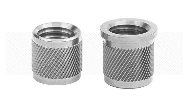
下载白皮书奥氏体镍不锈钢弹性圆柱销通常由 SAE 302/304 (18-8 (1.4310)) 等级的钢制成。这两个等级的钢在化学与物理特性上有所重叠,且许多工厂可生产通过此双重认证的材料。选用奥氏体不锈钢通常是为了抗腐蚀或降低成本。当此材料在插入,保持和工作时提供所需弹性的同时会有潜在的问题,在设计时须考虑。与直槽销相比,卷销具备诸多优势,某些优势在使用奥氏体不锈钢时尤为突出。
奥氏体不锈钢是某些应用的理想选择,尤其在需高耐腐蚀性应用中,奥氏体不锈钢可能不适用于主要用途为承受动态载荷的销。卷销和直槽销均是如此,因为此材料会迅速硬化。尽管工厂采用加工硬化实现高屈服强度,但关键需理解这是一个持续性的过程。随着屈服强度提高,延展性降低。在动态应用中,振动、冲击与移动都会持续以相同的程度和频率对销起到硬化作用。奥氏体不锈钢过度加工硬化会导致疲劳失效,表现为开裂或失去保持力。尽管 卷销与直槽销 都可加工硬化,但在这些情况下,优化设计的卷销可以提高耐力。

图1
直槽销与卷销
全部弹性圆柱销均以预装直径大于推荐标准孔直径的方式进行设计。直槽销制造时带有槽间隙,用于在安装时压紧销子。这点不同于以带缝形式设计的卷销(无间隙)。一旦安装,弹性圆柱销将处于拉紧状态并提供保持力。弹性圆柱销可以减弱振动与冲击,以防止销孔损坏或变形,从而保持所需要的配合和功能。直槽销仅可沿间隙对侧的销脊 180°弯曲,极其类似打开与合上书本。这使全部应力集中于单一位置(见图2),会造成急速疲劳损伤与潜在开裂(见图3)。同理,一旦金属丧失延展性,则无法恢复,从而在孔内失去张力,破坏保持力。
比较而言,卷销可分散应力至整个销且无应力集中点。负载情况下,卷销仍保持弹性并卷向中心,吸收冲击和振动,并将载荷分散至整个截面,如图4所示。卷销可在接缝处锁住不动,并且移动只发生在内圈。这起到两个重要作用:应力通过销的横截面均匀分布且销仍保持圆形,从而保持与孔壁的最大接触。

图2
直槽销高应力区

图3
直槽销仅可沿间隙对侧的销脊 180°弯曲,
极其类似打开与合上书本。
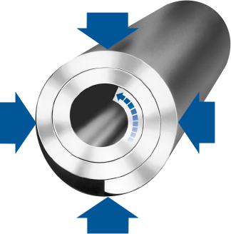
图4
卷销负载时的弹性
下图表示设计中的基本差异
图5表示直槽销装入推荐的标称孔径中。间隙虽小,但仍可能发生移动。这样可起到延缓加工硬化和疲劳损伤的作用,但不能避免。在本示例中,一旦直槽销在负载下完全受压至缝隙闭合,其功能将会与固定销管一样。这会损坏销孔。
在图6中,直槽销安装在超大孔内。在本示例中,鉴于间隙更大,销移动的可能性更大,疲劳损伤将会更快出现。
图7所示为与图5相同的推荐标称孔内装入相同直径的卷销。卷销较好圆度的优势显而易见。与直槽销典型的“泪滴”状不同,卷销的圆周接触仍保持最小270°。唯一间隙出现在邻接接缝处,此斜切边的接缝十分有必要,确保接缝边不会与孔壁接触,否则,会造成材料刮削。此区域以下简称逗点区(图8)。

图5
直槽销装入推荐的标称孔径中。注意:沿销内径缝隙实际上处于闭合状态。

图6
超大孔内安装直槽销

图7
推荐的标称孔径内安装卷销。

图8
A: 逗点区
B: 接缝的斜边
总之,尽管设计中必须考虑一些限制条件,但在某些应用中,奥氏体不锈钢仍可能是最节省成本的理想选择。加工硬化是首先要考虑的,但还有其他的问题也要考虑。电化学腐蚀/材料兼容性、抗特定腐蚀性物质/环境能力、反射率、磁性与其它考虑因素是不常见的,且与特定的应用有关。卷销设计于最广泛的使用条件下提供最佳性能。所有材料和载荷的卷销相对于直槽销均有优势,以奥氏体不锈钢材料制造的产品中尤为突出。如果需要用此材料,设计师必须意识到如果销在动态载荷下使用,始终存在疲劳损坏这个潜在问题。按照设计建议,卷销具备卓越的疲劳寿命。