

 CHINA
CHINA Malaysia
  한국
한국  USA
USA  Canada
  United Kingdom
  Deutschland
  México
  Brasil
  Česká republika
  France
  España
 Measurement Techniques for the Inspection of Series 550 Coiled Pins for Cosmetic Cases
Download this Whitepaper
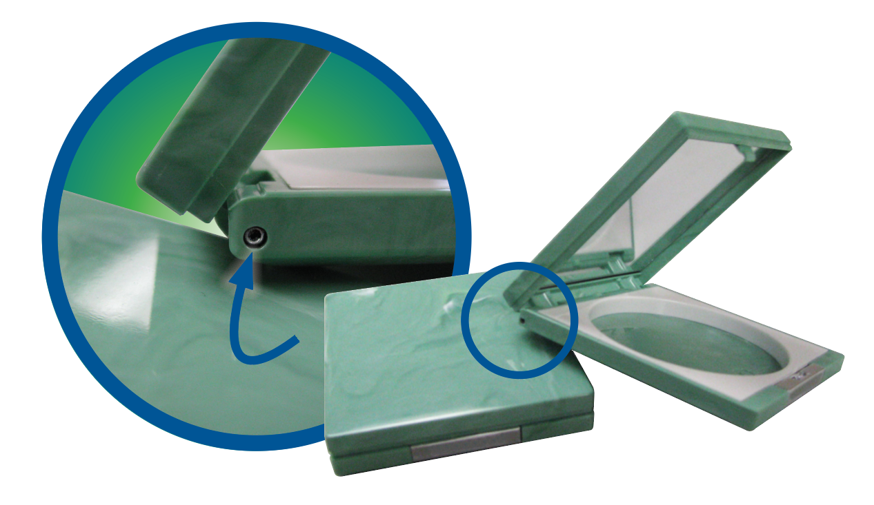
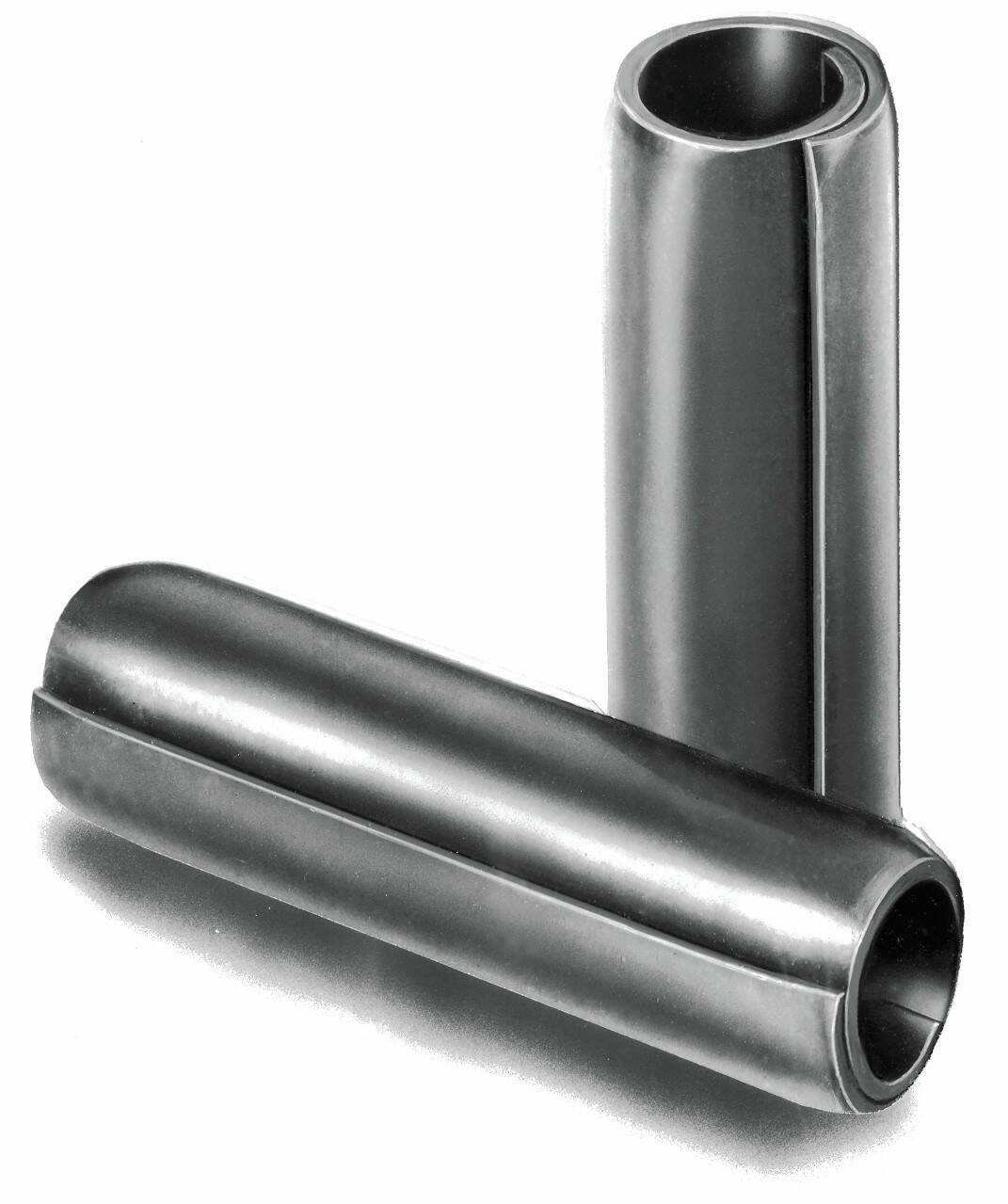
SPIROL® Series 550 Cosmetic Coiled Pins were designed specifically to be used as hinge pins in cosmetic cases. The seam of this extra light duty Coiled Pin is ‘tucked’ or rolled to ensure the pin remains round. In addition, the seam is prepared with a beveled edge to soften the transition into the ‘comma’ area (see Figure 1). A key characteristic of a Coiled Pin is that the diameter of the pin at the seam is equal to or less than the diameter adjacent to the seam. This prevents the edge of the material from contacting the inside diameter of the hole wall and prevents skiving when inserted. Once installed, the 1½ coil formation exerts the ideal amount of radial force to provide self-retention as well as the desired swing torque without damaging the plastic. Considering that the pin is a functional spring, it will absorb shock and vibration, isolating the plastic from excessive force that could open up the hole. The result is exceptional performance and preservation of the desired fit and function throughout the life of the product. These factors combine to make the SPIROL® Series 550 Cosmetic Coiled Pin ideal for hinges in cosmetic cases.

Figure 1
The Coiled Pin’s seam is prepared with a beveled edge to soften the transition into the ‘comma’ area.
This design feature ensures that there are no “high spots” at the seam.
A: Comma Area
B: Beveled Edge of Seam
Diameter Measurement
Diameter is measured utilizing a spline type micrometer (Fig. 2a) with reduced measuring faces. Standard micrometers (Fig. 2b) are too large and do not lend themselves to measuring such tiny parts. It is also highly recommended that a binocular magnifier/optivisor (Fig. 3) is used to ensure correct orientation of parts is achieved during inspection.
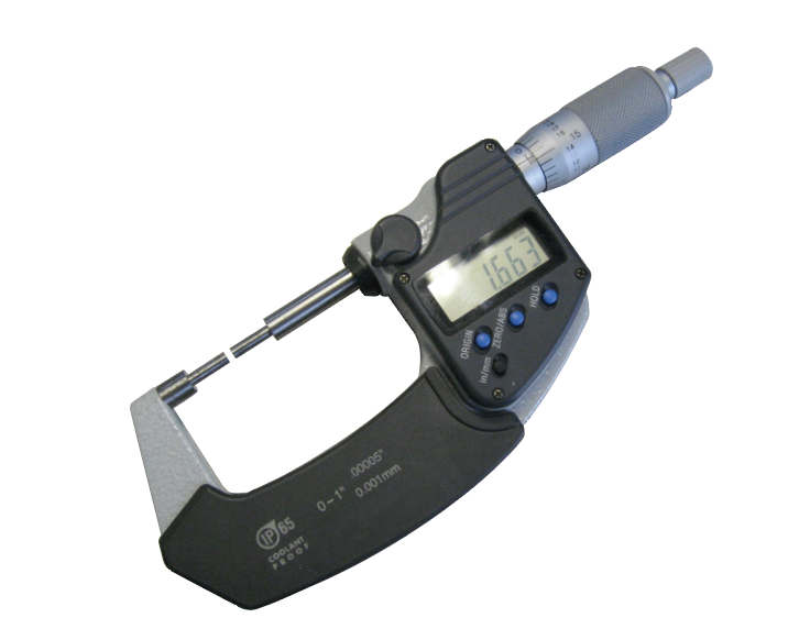
Figure 2a
Spline type micrometer with reduced measuring face
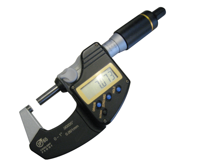
Figure 2b
Standard Micrometer
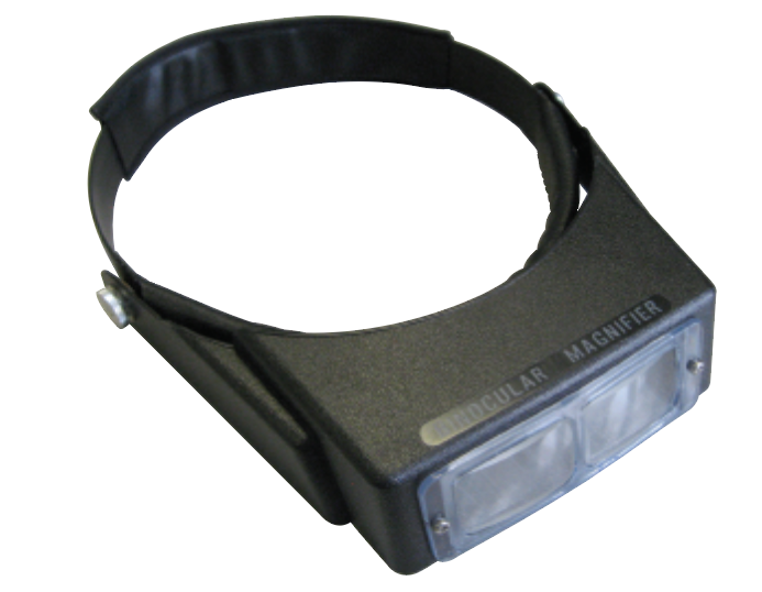
Figure 3
Binocular Magnifier/Optivisor
The Coiled Pin will be within specification over 270° of the outer circumference. Micrometer measurements are taken at 0°, 45°, and 90° to the seam as depicted in the diagrams below (Fig. 4). It is critical that the pin be centered between the upper and lower anvils and that the micrometer not be tightened beyond the point at which it contacts the pin. The tiniest amount of excess compression will yield an incorrect reading. Diameter is to be measured a minimum of one pin diameter in length from the end of the pin. This eliminates measurement error relating to the transition from chamfer to tenon diameter. For example, when measuring a Ø1.2 mm Coiled Pin, diameter would be measured no closer than 1.2 mm to the end of the pin.
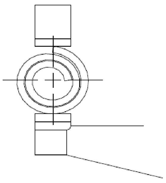
0°
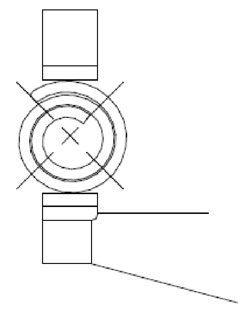
45°
Figure 4
Micrometer measurements
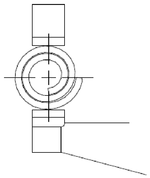
90°
The use of a micrometer stand will (Fig. 5) make it easier for the inspector to correctly locate the pin between the micrometer anvils and ensure no excessive pressure is applied during measuring. Hold the pin between the thumb and forefinger in the correctly orientated position and gently wind down the micrometer spindle until the anvils make contact with the pin.
Extreme care has to be taken while performing the inspection due to the extreme flexibility of the pin. Unlike when measuring more rigid components, contact with the pin should be determined more through sight using the optivisor (or other type of magnifying lens) and the initial feel of the pin between thumb and forefinger rather than feel of the micrometer spindle tightening onto the pin. If the micrometer can be felt “tightening down” onto the pin after the initial contact, it has been over-tightened and the reading will be false.

Figure 5
Micrometer in Micrometer Stand
Length Measurement
The length of a Coiled Pin is easily measured utilizing calipers. It is critical that the pin be positioned squarely between the anvils of the measuring tool. See the photographs below:

Chamfer Diameter (‘B’ Max)
The chamfer diameter or “B” (below) is designed to be smaller than the minimum recommended hole to facilitate insertion. This feature should be measured with an optical comparator. The easiest method by which to inspect the chamfer diameter is to either lay the pin horizontally in a v-block (Fig. 6a) or mount the pin vertically in modeling clay or plumbers putty (Fig. 6b) for support. Place the pin and mounting device on the comparator stage. If using the v-block, locate the y axis of the projection screen crosshair on the extreme edge of the chamfer. If using modeling clay, locate the x axis of the projection screen crosshair on the extreme edge of the chamfer. Zero the measuring mechanism before relocating the crosshair to the opposite edge of the chamfer. This will yield the chamfer diameter.
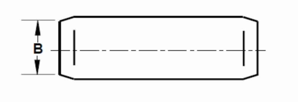
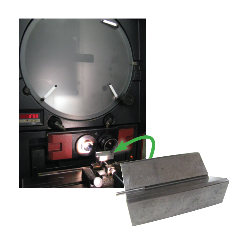
Figure 6a
Pin in v-block and optical comparator

Figure 6b
Pin in modeling clay and optical comparator
Design Guidelines for Cosmetic Cases
SPIROL Series 550 Cosmetic Pins
The use of a Series 550 Cosmetic Coiled Pin will simplify design as misalignment of the inner and outer holes to provide friction is no longer necessary. Intentional misalignment is difficult to control in production and induces stress in the hinge area causing cracking and pin fallout. Below are some guidelines that should be followed when designing cosmetic cases:
Ideally, all of the holes in the cover and base would be sized identically.
- If it is not possible to have identical hole sizes in the cover and the base, the tolerance may be divided between the outer and inner holes as follows:
- Outer holes = Smaller half of tolerance
- Inner holes = Larger half of tolerance
- Misalignment should not exceed 0.05 mm.
- 60% or more pin length retained by the inner boss.
- Minimum bearing surface in either boss should exceed three times the diameter of the pin.
- The inner boss hole depth should be at least 0.38 mm deeper than the retained pin length to prevent breaks at assembly.
- The minimum boss diameter should be two to three times the diameter of the pin to ensure adequate wall thickness.
SPIROL Model HC Horizontal, Dual Pin Inserter

Designed to install SPIROL Series 550 Coiled Pins into plastic hinges