The Difference Between Coiled Spring Pins and Slotted Spring Pins
By
Download this WhitepaperWhat is a Spring Pin?
A Spring Pin, also often referred to as Tension Pin or Roll Pin, is a mechanical fastener used for securing two or more parts of an assembly together. Spring Pins are hollow, tube-like parts designed to be larger than the hole and are made from various types of spring steel or other materials.
The primary difference of a Spring Pin compared to a classic Solid Pin is that its radial stiffness is significantly lower than the host material. Solid Pins can have a smooth, uninterrupted surface (such as dowels) or they may be designed with retention features such as grooves, knurls or barbs. Solid Pins are commonly retained by displacing/deforming the host material. However, in cases when the pin is precision ground and the hole is precision reamed, the fit of a Ground Solid Pin can be very tightly controlled between a slight amount of clearance and a small amount of interference which will not result in the displacement of material from either the pin or the host. However, the precision grinding and reaming of both the pin and the hole makes this pinning option one of the most costly.
Spring Pins, on the other hand, can absorb a much larger hole tolerance than rigid Solid Pins. Thanks to their flexibility, not only are Spring Pins less expensive to manufacture, but the hole preparation is also less tedious and less expensive. The comparatively lower stiffness also brings another benefit – Spring Pins do not damage the host hole (when properly selected) – so much so, that they can be serviced without the need of reworking the parts.
There are two basic types of Spring Pins – Slotted Spring Pins and Coiled Spring Pins.
Slotted Spring Pins
A Slotted Spring Pin is characterized by its C-shape cross section and a slot running parallel to its axis. While their precise origin is unknown, they have been appearing as a concept in mechanical devices throughout modern history. Over time through various industry standards, they have developed into what is commonly used today in many different types of applications. There are several active industry standards, but four (4) prevail and account for the majority of Slotted Pin demand: ASME B18.8.2, ASME B18.8.4M, ISO 8752 and ISO 13337.
Coiled Spring Pins
A Coiled Spring Pin is recognized by its 2¼ coils cross section. The history of the Coiled Pin is much clearer. It was invented in 1948 by Herman Koehl, SPIROL’s founding father, specifically as a solution to an application with harsh vibrations and dynamic loads – a rotor of a jet engine. Unlike other traditional fasteners such as nuts and bolts which tend to loosen under severe vibration, or rigid Solid Pins which transmit the dynamic loads to the hole wall and compromise retention of the pin, Mr. Koehl designed a pin that was strong enough to resist the forces generated during use, yet also flexible enough to absorb the forces so as to preserve the integrity of the hole material and keep the assembly intact. The Coiled Pin is available in three different duties for the optimal combination of strength and flexibility to accommodate different types of applications and host materials. The most common industry standards for Coiled Pins are ISO 8750, ISO 8748, ISO 8751 and ASME B18.8.2 and ASME B18.8.3M. These standards do not differ a lot between each other and are considered to be virtually equivalent.
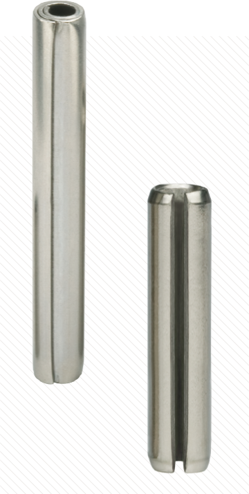
Coiled Spring Pin (left) &
Slotted Spring Pin (right)
Physical Features & Differences
Cross Section
The main difference between a Coiled Spring Pin and Slotted Spring Pin is in the cross section as shown in Figure 1. While the Slotted Pin is a C-shaped pin usually rolled from a thicker strip of material, the Coiled Pin is rolled from a thinner strip to achieve its typical 2¼ coils cross section for the same nominal diameter. The key implication of this difference is the pin’s flexibility. A Slotted Pin can only flex so much before it closes its gap and effectively becomes a stiff, solid tube. The slot allows the Slotted Pin to absorb manufacturing tolerance of the hole during installation, but shock and vibration after installation are not dampened because further flexing is limited by the closed slot. This can lead to premature failure of the joint and damage to the host component.
A Coiled Pin, on the other hand, can flex even beyond its initial installation interference given the virtually unlimited flexibility of the coils. In fact, when the proper Coiled Spring Pin is selected for an assembly, the pin will indefinitely absorb vibrations and shock forces and protect the hole material to maximize the useful life of the assembly.
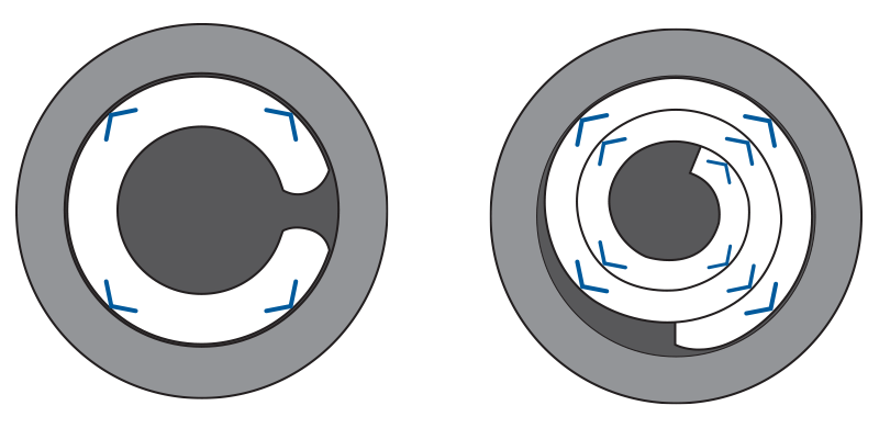
Figure 1
Cross section of a Slotted Spring Pin (left) and Coiled Spring Pin (right) showing the difference in Radial Tension
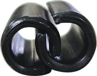
Figure 2
Example of interlocked Slotted Spring Pins
Slot/Seam
Another key differentiator is the design of the edge where the steel strip ends. With a Slotted Pin, this is the slot. In some configurations, the slot is as wide as the strip thickness itself (ISO 8752), which means that the pins can interlock or nest within each other as seen in Figure 2. These types of Slotted Pins should be avoided in highly automated assembly lines as this will result in jammed feeding equipment.
A Coiled Pin, with multiple wraps of material, has a smooth seam rather than an open slot (Figure 3). Not only does the enclosed cross section prevent interlocking or nesting, but it also provides a smooth surface for rotation, which is especially useful in hinge applications. Another benefit of having a more uniform cross section is that a Coiled Pin’s strength is not orientation dependent. This is not the case with a C-shaped Slotted Pin where its shear strength can vary by approximately 5%, in favor of the load being aligned to the slot (0° or 180° (Figure 4)).
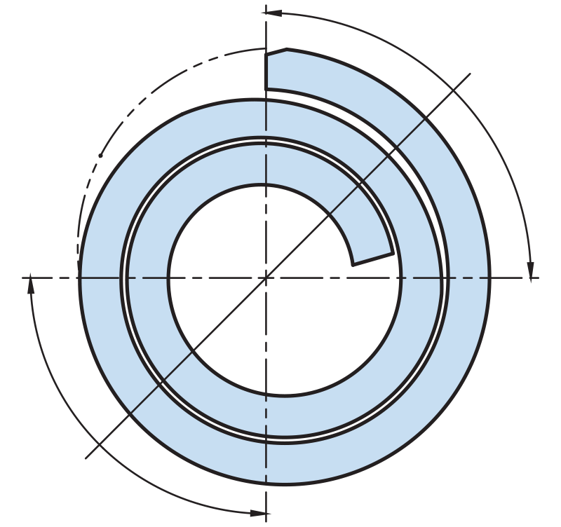
Figure 3
Cross section of a Coiled Spring Pin
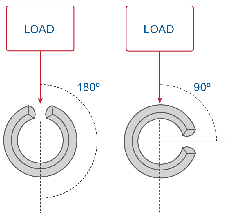
Figure 4
Orientation of the slot affects shear strength in Slotted Spring Pins by approximately 5%
Chamfer
Some configurations of Slotted Pins have a chamfer diameter specified simply as “less than the nominal pin diameter” (ISO 8752). This prevents the pin from pre-aligning itself with the hole prior to installation and prevents the pin from compensating for misalignment between the pinned parts. Other Slotted Pin industry specifications have a more controlled chamfer diameter designed to be smaller than the hole with a margin specifically to facilitate assembly.
All Coiled Pins have chamfers specified as smaller than the hole with a specific margin. A Coiled Pin’s chamfer is swaged with a smooth transition to facilitate trouble-free assembly.
Square Ends
Due to the different manufacturing methods, Slotted Pins can often have ends not perfectly perpendicular to their axis due to the manufacturing method. This can present an obstruction in automatic feeding where pins stacked atop each other can grab the neighboring parts and cause a jam. This can also be caused by small “nibs” of material sometimes present at the end of the pin resulting from the manufacturing process (Figure 5).
Coiled Pins have square ends that enable them to self-align with the installation punch/quill. This ensures the pin remains straight and that uniform force is applied during installation into the hole.
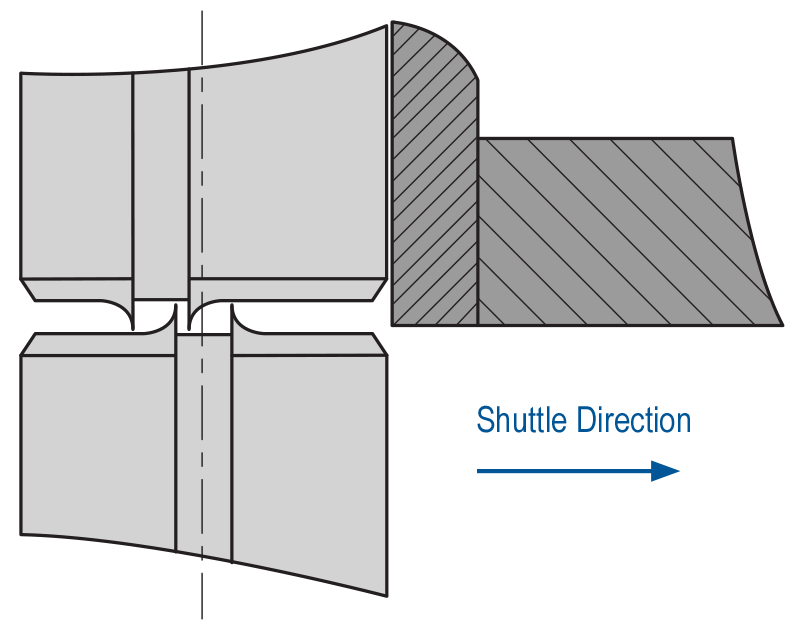
Figure 5
Some Slotted Pins have small “nibs” of material that can lead to jams in automatic feeders
(exaggerated for demonstrational purposes)
Pin Recommendations Based on Application
Dynamic Applications
When it comes to dynamic applications, the Coiled Spring Pin outperforms all other types of press-fit pins. In dynamic applications, the pin endures vibrations, shocks or impacts and it needs to be able to absorb them in order to achieve the longest service life.
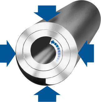
Figure 6
Coiled Spring Pins remain flexible after installation, absorbing shock and vibration, and extending the life of the assembly
Coiled Pins were specifically designed to remain flexible after insertion and absorb the changing loads and vibrations (Figure 6). Studies have shown that the Coiled Pin clearly outperforms the Slotted Pin in fatigue testing in both – 1) the ultimate load for an infinite life, and 2) cycles until failure at a set load.
A Slotted Pin has very limited flexibility – most of which is consumed during installation. Once installed, Slotted Pins have very little gap width left to absorb any changing loads. When the slot closes, the Slotted Pin becomes a stiff, solid tube and acts similarly to a Solid Pin where it transfers the load directly to the host. This can damage the hole, rendering the parts unusable or in need of reworking.
There’s another factor which affects the service life of Slotted Pins – slot orientation. Through testing, it has been found that the service life of a Slotted Pin can decrease by roughly 50% when the slot is oriented 90° to the load (Figure 4).
The service life of a Coiled Pin, on the other hand, is orientation independent.
Automatic Assembly
For highly automated environments, it is critical to achieve consistent quality of installation and prevent line stoppage. Due to the combination of unique features, the Coiled Pin is best suited for highly automated environments as its lack of slot, square ends, swaged chamfers and consistent installation force facilitates trouble-free installation and minimal downtime. In addition, the performance of a Coiled Spring Pin is not affected by its orientation to the applied load.


 CHINA
CHINA Malaysia
  한국
한국  USA
USA  Canada
  United Kingdom
  Deutschland
  México
  Brasil
  Česká republika
  France
  España