
 CHINA
CHINA Malaysia
  한국
한국  USA
USA  Canada
  United Kingdom
  Deutschland
  México
  Brasil
  Česká republika
  France
  España
 Absorbing Centerline and Stack-Up Tolerances with Oval Compression Limiters
By
Download this WhitepaperCenterline Tolerancing
When assembling multiple components with two or more fastening/joining points, there is an increased importance on the location of the Compression Limiters within the plastic component. Compression Limiters must not only align with the mating components, but also maintain a defined centerline tolerance with each other. (Centerline tolerance defines the maximum allowable misalignment between two or more components in an assembly.) This will ensure that the accumulated misalignment remains within acceptable limits so the components maintain their relative positions and can be securely fastened at multiple points within the assembly.
Tolerance Stack-Up
Tolerance stack-up is the accumulation of multiple individual part tolerances that, summed together, result in the overall tolerance. It is important to understand the cumulative effect on the part production and the assembly process. For example: Will both fastening points align at the minimum and maximum stack up tolerance?

Example 1
The Design Engineer of an assembly needed to account for the stack-up centerline tolerances of several fastening points. The requirement of the assembly in Figure 1 was such that there could be no movement up and down along the y-axis. Therefore, the product designer decided to use (1) Round Compression Limiter as a datum point, which would be installed first to ensure correct overall positioning. Next, they redesigned the assembly to replace the (3) Round Compression Limiters with Oval Compression Limiters to account for any deviations from centerline along the remaining (3) fastening points (Figure 2).
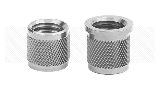
Round Compression Limiter
Oval Compression Limiter
Host component
Plastic component

Figure 1
Round Compression Limiters provide precise alignment but do not accommodate stack-up tolerances.
A = Centerline of host component

Figure 2
SPIROL’s Oval Compression Limiters compensate for misalignment by providing an extra 2.25mm of clearance on one axis.
B = (1) Round Compression Limiter used as a homing fastening point
Oval Compression Limiters
A solution to account for stack-up tolerance while maintaining centerlines of the assembly is to use Oval Compression Limiters. SPIROL’s CL400 Split Seam and CL460 Molded-In Oval Compression Limiters provide 2.25mm of extra clearance on one axis, providing additional flexibility over Round Compression Limiters for centerline and stack-up tolerancing. The forming process used to manufacture these oval parts generates little-to-no scrap and allows for high production speeds, resulting in a significantly lower costs compared to machined, cold headed, or powdered metal parts that can have costly unused material (scrap) or slower production output.
Strategic Selection of Oval and Round Compression Limiters
If the mating component has known tolerance deviations along a certain axis, causing potential misalignment at specific fastening points, Oval Compression Limiters can be used strategically in combination with Round Compression Limiters (Figures 2 & 4). This flexibility gives the product designer of the plastic component the ability to provide solutions when alignment challenges present themselves – especially if they do not also have design control of the mating component. Round Compression Limiters serve a valuable purpose in the combination as well. In assemblies with multiple fastening points, designers do not necessarily want too much flexibility along one axis. That could lead to, for example, the entire plastic component sitting too far to one side of the mating component. Therefore, there is value in the clearance limitations of Round Compression Limiters – they keep the overall alignment of the assembly centered while the Oval Compression Limiters alleviate the issue of potential misalignment on specific, targeted, fastening points.
Example 2
There are (4) fastening points in a rectangular sequence. This leads to the possibility of misalignment along the x and y axis (Figure 3). The product designer has opted to place an Oval Compression Limiter diagonally in one of the corners (bottom right) to account for the potential misalignment (Figure 4). During assembly, the fastening points with the (3) Round Compression Limiters can be secured first, then any misalignment between the plastic component and the mating component will be accommodated by the Oval Compression Limiter at the final fastening point.

Figure 3
Misalignment of the final fastening point (bottom right) may cause issues during assembly.
Figure 4
An Oval Compression Limiter placed diagonally in one corner accounts for misalignment.
Conclusion
Given the number of Compression Limiter options available, it is recommended to consult SPIROL’s Application Engineers, who specialize in Compression Limiters, to ensure the correct selection for your specific assembly. With nearly 80 years of fastening and joining experience, SPIROL is ready to support your next project!


