
 CHINA
CHINA Malaysia
  한국
한국  USA
USA  Canada
  United Kingdom
  Deutschland
  México
  Brasil
  Česká republika
  France
  España
 Choosing the Proper Fastener when Automating
By
Download this WhitepaperThe fastener is as important when automating as the automation equipment itself. Choosing the right fastener may prevent exorbitant machine and fixture costs, decrease set-up and cycle times, as well as reduce the manufacturing cost of the components.
One of the biggest motivators for companies who choose automatic fastening over manual fastening is increasing productivity and reducing costs. Unfortunately, many don’t realize the impact the fastener has on achieving these goals. Not all fasteners are easy to orient, feed, or install. Also, the more tooling necessary to orient and deliver the fastener, the more expensive the equipment is going to be. It is important to select a fastener that meets the application requirements and is conducive to automation in order to maximize productivity and minimize costs.
It is in the design stage of the assembly where the decisions are made that will either make or break the success and ease of automation. A common mistake that is made is when designs allow the cost of the fastener to take precedence over the cost of fastening. Any money saved on the cost of the fastener can be quickly eroded by the money spent on intricate automation equipment, and decreased productivity through increased assembly cycle times, and equipment downtime. Companies should focus on the lowest installed cost fastener. Typically, these are permanently installed fasteners that are pressed into, rather than threaded into, a hole and do not require any secondary operations for retention.
There are a few general considerations to keep in mind when considering automating fastener installation. The length to diameter ratio of the fastener is very important. Any part with a length to diameter ratio less than 1:1 can be problematic because there is potential for the parts to tumble and jam in the feed tube. It is also recommended that the fasteners are clean and sorted. Dirty fasteners not only cause some parts to stick in the feeder bowl, but they can also stick in the feed tube. If the fasteners are not sorted, there is a potential of jamming the insertion equipment. This can be costly because valuable time is wasted breaking down the machine to clear the jam.
Design engineers and assemblers should become familiar with the features of fasteners that can affect the success of automating. For the sake of this discussion, the features have been broken down into symmetrical and non-symmetrical.
Non-Symmetrical
Non-symmetrical fasteners can be a challenge to automate depending on the feature(s). They require end to end orientation; thus more expensive tooling is necessary than required for symmetrical fasteners.
In order to utilize traditional automating methods, headed parts should be able to hang by the head. A good rule of thumb is that there should be a minimum of a 20% differential between the head and body diameter in order to provide enough distinction to allow for orienting and hanging the parts. If differential the diameter can be held between 20%-30%, additional tooling costs can be avoided. Headed parts that do not have a consistent head diameter, or are inconsistent beneath the head tend to get jammed on the feed rail. Flat heads are also better than round heads for automatic installation. This is because it is easier to press a flat insertion quill onto a flat surface versus a round surface while keeping the fastener straight at the same time. The added costs to feed, orient, and install headed fasteners make it fundamental to ensure that the application truly requires a headed fastener before specifying one.
Non-headed, non-symmetrical fasteners must also have some differential in order to use the traditional feeding method of hanging on a set of rails. This differential can be a 20% difference between body and feature diameter, or a significant weight imbalance of at least 10% between the ends of the fastener. (Basically, when put in a set of rails, the natural tendency of the fastener should be to fall in one particular direction every time.) If this is not the case, a more complex method of orienting is necessary. There are several methods to choose from: vision, laser, optical sensor, or a gaging bushing. However, by using a symmetrical fastener companies can save significantly on the cost of the automation equipment.

Symmetrical
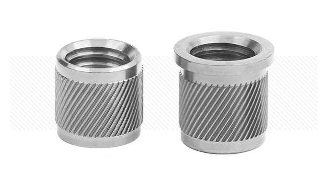
Fasteners that are symmetrical and have a continuous profile are ideal for automating. They are the easiest to feed because they require minimal orientation. Basically, all you need is a machine that will deliver the parts in a straight line to the feed tube. Once oriented, these parts are typically fed in a tube down to some type of insertion equipment. Some examples of these include straight (dowel) pins, grooved pins, knurled pins, slotted spring pins, and coiled spring pins.
There are some disadvantages associated with some of these fasteners. For example, the straight dowel pin is highly dependent on the host material for retention. This means that the cost of the hole preparation can be expensive since reaming is required to achieve the necessary tight tolerances. (The exception is when these pins are used in plastic, because the holes are molded.)
To compensate for some of the disadvantages of the straight solid dowel pins, the grooved pins and knurled pins were developed. The diameter across the grooves and knurls is designed to be larger than the hole. When a hardened grooved pin is used for strength, the host material deforms but not to the same extent as a straight solid pin. The knurled pin is designed to cut its way in the host component, however neither the knurled nor the grooved pin requires the tight tolerances that the straight solid pins do. Regardless, insertion forces are usually much higher for all types of solid pins, which can dramatically affect the cost of the automation equipment. In addition, since solid pins require deformation of the host material for retention, there is the possibility for cracked and/or damaged components during the installation process.
To compensate for the disadvantages of the solid pin, the spring pin was developed. When a spring pin is driven into a hole, the spring action of the pin allows it to compress as it assumes the diameter of the hole. Once installed, the radial force exerted by the pin against the hole wall provides selfretention. Since spring pins do not require deformation of the material for retention, there is no host component damage and installation forces are lower. In addition, the spring pin is able to absorb hole tolerances and minor hole mismatch. There are two types of spring pins: slotted and coiled.

empty

Slotted pins are manufactured with a gap to allow the pins to flex. Some manufacturing processes, such as the roll forming method, result in uneven chamfers and non-square ends. The slotted pin is a great way to reduce costs when manually installing the fastener, however when automating, it is highly recommended to avoid this pin. The biggest problem when automating the slotted pin is the non-square ends. The problem associated with this feature is that when entering the escapement in the installation machine, the slotted pin tends to catch on the pin above it in the feed tube, which prevents pin advancement. The gap can also cause the slotted pins to interlock and jam in the pin inserter. The manufacturing method of roll forming this product induces the possibility of a bowed or banana shaped part. The pins tend to stretch at the slot and contract 180 degrees from the slot. The stresses imparted to the pins in the heat treating/quenching process also tend to distort the pins. If the pin is not straight, it will not pass through the discharge bushing in the feed bowl, therefore never make it into the feed tube. Finally, in order to maximize strength, the slotted pin must be oriented such that the applied force passes directly through the gap. This can be tricky to automate, and will be expensive.
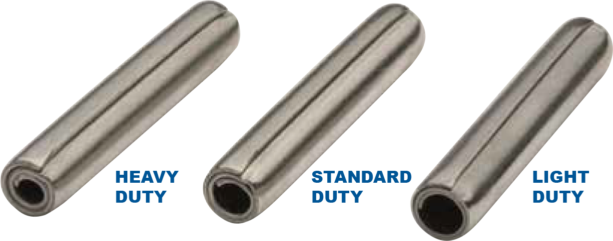
In order to compensate for the disadvantages of both the solid and slotted pin, the Coiled Spring Pin was developed. These pins are manufactured from strip material, and rolled into a spiral spring of 1-1/2 or 2-1/4 coils. There are many features to this pin that contribute to trouble-free automation. Coiled pins cannot nest or interlock because there are no gaps. In addition to the spring nature of the pin, the square, clean-cut ends, combined with a smooth, concentric lead-in chamfer and a blended radius eliminates any sharp edges or angles that may “bite” into the hole wall, thus reducing insertion forces. The chamfer concentricity assists in alignment with the host and mating holes. In addition, this pin does not have to be oriented for strength. These important attributes can significantly reduce down time during the production process, decrease equipment costs, and yield trouble free assembly.


The duty (or material) thickness of the coiled pin can be varied to provide the optimum combination of strength and flexibility. The lighter duty pins require less insertion force, thus reduces the cost of the automation equipment because a smaller cylinder and/or machine can be used. In applications where this pin is appropriate, the ease of automation makes this the lowest installed cost fastener.
Keep in mind that just about anything can be automated, provided that there is enough time and money. By adhering to the following basic guidelines, companies will be able to increase productivity and avoid unnecessary tooling costs associated with complex automation equipment.
- Specify fasteners with a length to diameter ratio greater than 1:1.
- Ensure that the fasteners are clean and sorted.
- Utilize symmetrical fasteners whenever possible. This includes avoiding fasteners that must be oriented for strength.
- Use fasteners that require low insertion forces, (while still providing adequate retention).
- Design in fasteners that allow for greater hole tolerances.
- If a headed fastener is necessary, design the fastener such that the differential in the head and body diameter is between 20%-30%.
By considering the fastener during the design stage, companies can implement automatic fastener installation at the lowest installed cost.