
 CHINA
CHINA Malaysia
  한국
한국  USA
USA  Canada
  United Kingdom
  Deutschland
  México
  Brasil
  Česká republika
  France
  España
 Fastening Solutions for Medical Devices
By
Download this WhitepaperEven though they tend to be the smallest components in the medical device, fasteners are usually the most important element of the assembly as they literally hold the entire unit together. When a fastener fails in a medical device, this usually means that the device will also fail. The correct fasteners ensure that the device goes together and stays together for the intended life of the assembly, and that the device performs as desired.
All too often, these critical elements end up being the very last thing that Engineers consider in the design process. As a result, fasteners used in medical devices are usually specified as extremely tightly toleranced parts. In addition, due to the unfamiliarity of the various fastener industry standards and associated manufacturing processes, Engineers frequently tie the hands of the fastener manufacturer into using highcost manufacturing processes to meet the specifications.
What most people do not realize is that the Design Engineer plays a significant role in the profitability of a company through the fasteners that they select. Fasteners can overcome challenges in assembly, solve quality problems and significantly reduce the total cost of the device. Engineers can lower design and assembly costs by working directly with knowledgeable fastener manufacturers early in the design stage in order to ensure the most cost-effective components are designed into the device without having to go through costly redesigns after the product has launched.
Even though the importance of the fastener is evident, surprisingly, traditional Engineering curriculums do not contain any formal instruction on the proper methods of joining and assembly. This article will focus entirely on what designers and manufacturers need to know, avoid, and do, when it comes to pinning and spacing requirements in medical devices.
Consider Cold-Headed Versus Machined Pins
In the process of working with one surgical device manufacturer, it was discovered that they were using seven different machined Solid Pins as free-fit axles in their surgical stapler. The pins were slip fit into place and held in position by a plastic shroud that went entirely around the outside of the device. The pins were specified with an outer diameter (OD) tolerance of ±.001” and a length tolerance of ±.003”. The material of the pin was specified as 303 stainless steel (SST). Since this type of stainless is only readily available in bar stock, this essentially dictated that the parts had to be machined rather than cold headed or roll formed – two significantly less expensive production methods.
After a thorough review of the performance requirements, the medical device manufacturer agreed to widen the length tolerance to ±.010” (the difference of approximately 2 to 3 human hairs), as well as change the material specification from 303 SST to 305 SST so that commercially available wire could be used. These two changes enabled the pins to be cold headed versus machined with no change in performance of the assembly. The cold heading process yields extremely high Cpks. As a result of replacing the machined pins with cold headed pins, the medical manufacturer will save over $2.3 million dollars annually once the device reaches its full production volume.

Figure 1
Surgical Stapler
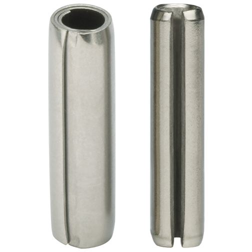
Figure 2
Coiled Pins have 2 ¼ coils of rolled material. Slotted Pins have a “C” shape.
Spring Pins
There are two distinct types of Spring Pins: Coiled Spring Pins and Slotted Spring Pins. Both types share certain characteristics such as flexibility and their ability to accommodate wider hole tolerances than nonflexible fasteners (such as Solid Pins). However there are a few major differences between the two types of Spring Pins that must be understood – particularly for medical device manufacturers.
Slotted Pins
While the Slotted Pin’s flexibility can reduce manufacturing costs by absorbing wider hole tolerances, there are several disadvantages to Slotted Pins that limit their applicability in medical applications. The Slotted Pin is significantly less flexible than the Coiled Pin and it only flexes 180º from the gap. This limited flexibility can result in plowing and debris generation during the installation process. Under load, the stress is concentrated 180˚ opposite the gap in Slotted Pins, which can cause premature failure of the assembly. Slotted Pins are also very difficult to automatically feed and install as they have uneven ends and excessive slot widths that can cause interlocking of the pins. The most appropriate applications for Slotted Pins are non-critical industrial assemblies, manufactured out of mild to hardened steel that are manually assembled.
Coiled Pins
Coiled Pins were originally invented to compensate for the deficiencies associated with Solid Pins, Slotted Pins and other conventional fasteners such as rivets, nuts and bolts. Easily recognized by its unique 2¼ coil cross-section, Coiled Pins are self-retaining pins that compress when installed into the host component. They are the only pins with uniform strength and flexibility after insertion. Truly an “engineered-fastener”, the Coiled Pin is available in three “duties” to enable the designer to choose the optimum combination of strength, flexibility and diameter to suit different host materials and application requirements. Their shock absorbing design dampens forces and vibration to prevent hole damage and prolong assembly life. Coiled Pins have square, burr-free ends and lower insertion forces than other pins, which make them ideal for automated assembly systems. The features of the Coiled Spring Pin make it the industry standard for applications where product quality and total manufacturing cost are critical considerations.
Y: Total hole tolerance
X: Diameter
A: Coiled Spring Pins
B: Slotted Spring Pins
C: Solid Grooved Pins
D: Solid Dowel Pins

Figure 3
Coiled Spring Pins and Slotted Spring Pins absorb wider hole tolerances than rigid Solid Pins.

Figure 4
Plexiglass sample shows the stresses exerted by light, standard and heavy duty Coiled Pins and Slotted Pins.
Figure 4 clearly articulates the differences between the radial force exerted by Slotted Pins and the three different duties of Coiled Pins. The wavy lines observed around each pin in the Plexiglass boss represent the stresses exerted by the pins. The larger the pattern, the higher the stress exerted by the pin. Notice that the size of the stress pattern is the smallest for the light duty Coiled Pin and the pattern gradually increases for the standard and heavy duty. Heavy duty Coiled Pins and Slotted Pins can have similar stress magnitudes – neither of which would ever be recommended for plastic applications. However, the stress distribution of the Coiled Pin is much more evenly spread out than that of the Slotted Pin where there are two regions of maximized stress denoted by the arrows on the image. The uniform radial force exerted by the Coiled Pin results in better retention and prolonged assembly life.
A: Heavy
B: Slotted
C: Standard
D: Light
Solving Quality Issues with Coiled Pins
A medical device manufacturer was previously using a machined knurled Solid Pin in a surgical “grasper” used to allow the surgeon to operate through a laparoscopic port versus having to fully open up the patient to perform the procedure. The pin is used to drive the jaw movement at the distal end of the device. The high insertion force of the rigid Solid Pin deformed the pin, damaged the assembly, and generated metallic debris. As this device is used inside the human body the presence of metal shavings is unacceptable.
The Knurled Pin, made from 303 SST with no subsequent heat treatment, was installed into a hardened 416 SST shaft. The combination of the incompatible hardness and the variation in size between the pin and host material were determined to be the root causes of the debris generation, high insertion force, pin bending, and associated subassembly damage.
To address all of these issues, the manufacturer replaced the Solid Pin with a heat treated, 420 SST light duty Coiled Spring Pin. A light duty Coiled Pin provided the appropriate balance of strength and flexibility to facilitate a low insertion force while providing adequate retention without damaging the hole and generating debris.
In addition to permanently resolving the quality issues caused by the Solid Knurled Pin, the medical device manufacturer also benefited from a significant cost reduction associated with switching from a machined Solid Pin to a roll formed Coiled Pin.

Figure 5
The knurled Solid Pin generated debris during insertion into surgical “grasper”. The Coiled Spring Pin installed cleanly.
A: Knurled Solid Pin
B: Coiled Spring Pin
Low-Cost Spacing Solution
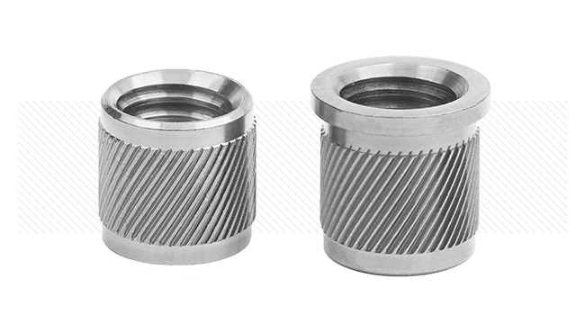
Roll formed metal Spacers are a great low cost alternative to cut-off tubing, tubes, grommets and turned or machined parts. They are commonly used as stand-offs, distance bushings, sleeves, axles and pins. Roll formed Spacers are produced without any burrs or debris generation and have clean-cut, square-ends; very important characteristics of components used in medical devices.
Manufacturers commonly use machined Bushings and cut tubing to space two thin stainless plates from each other in medical devices. It is customary to pass a rivet through the ID of the machined Bushing or tubing to hold the two plates in constant compression such that they stay parallel to each other throughout the life of the device. This simple spacing application is very common in the medical industry, and one that can be easily changed to utilize a roll formed Spacer without any negative effects of performance. The result of converting from cut-tubing to a roll formed Spacer is usually a cost savings of approximately 50%, and roll formed Spacers are typically 1/10th the cost of machined Bushings.

Figure 6
Partnering with Knowledgeable Suppliers
In addition to choosing a high quality fastener manufacturing company that has a diverse product offering, it is equally as important to work with a company that has vast Application Engineering knowledge in the realm of joining and assembly. By partnering with knowledgeable, Application Engineering oriented suppliers in the design stage, they will not only facilitate the design of the engineered fastener, but they will also make the critical recommendations for the interface between the fastener and the medical device.
The earlier the supplier is brought into the design process, the more likely they will be able to equip the device manufacturer with a commercially available fastener. Usually, there are many different types of fasteners that could be used for each application. Ultimately, the most cost-effective solution takes into consideration the host material, manufacturing tolerances, application requirements and method of assembly.
The benefits of specifying commercially available parts are that parts can often be delivered from stock, there are no minimum purchase requirements, and no tooling or development charges. This means that parts can be delivered quickly – whether they are required for the prototype stage or full production requirements.
Ultimately, Designers should utilize engineered fasteners that enhance the quality of the medical device, simplify the assembly process and result in the lowest total cost.

Figure 7
Roll formed metal Spacers are much more cost-effective than machined Bushings or Cut Tubing.