The Advantages of Using Light Duty Coiled Spring Pins Versus Slotted Spring Pins in Assemblies with Soft Materials
By
Download this WhitepaperIn recent years, the tendency throughout industry has been to explore the use of new materials in order to reduce weight and process cost, or to provide solutions where more traditional materials such as steel, machined components or castings would not perform as well.
Under those considerations, the use of plastic, aluminum and soft alloys has seen an exponential increase, and nothing seems to indicate that this trend is going to stop. On the contrary, as plastics and molding processes continue to advance, more and more applications that were traditionally made in steel are being reviewed to overcome the issues that prevented the use of these lighter, softer materials that provide equal or even better performance.
We can currently find numerous plastic components being used in demanding situations such as high temperature, high strength and chemical resistant applications. However, although the main component receives significant design attention and consideration, the mating components and the fastening method are habitually neglected until the end of the project. Also, it is routinely assumed that parts and design concepts that previously worked in steel will work with the softer alloys and plastics.
When it comes to pinning applications in new materials, it is frequently a situation of going for the cheapest option and what is known in the industry. In many cases this is the (heavy duty) Slotted Pin per ISO 8752 (also known as the roll pin), which has been around for many years, developed from the old DIN 1481 standard. This pin was designed long before the advancements in production techniques and materials made lightweight / high-volume production feasible. The ISO 8752 Slotted Pin can and does, in fact, create significant assembly and quality issues in these new materials. Its thick wall, combined with an out-of-round or horse-shoe shape, does not provide the required flexibility for its use in relatively soft materials—often transferring the load from the pin to the wall of the host assembly, thereby damaging the hole, and resulting in premature assembly failure. In an attempt to reduce the disadvantages associated with the heavy duty Slotted Pin per ISO 8752, a light duty Slotted Spring Pin per ISO 13337 was designed. The main difference is the thickness of the pin wall. A thinner wall means increased flexibility, but also reduced shear strength, while other important issues remain unresolved. In fact, the thinner wall in and of itself creates new additional limitations with respect to fatigue resistance.
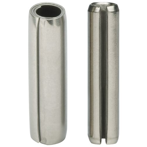
Figure 1
Light Duty Coiled Pin (left) &
Slotted Spring Pin (right)
Light duty (ISO 13337) Slotted Spring Pins, similar to the more common heavy duty Slotted Pin (per ISO 8752), present a horse-shoe shape cross-section which will, in many instances, create skiving during insertion into the hole. Coupled with that, the expanded diameter of the pin in relation to the size of the hole has the effect of creating a pin with a very wide slot. The result is a pin with an insertion force, and subsequent radial pressure against the wall of the hole, that will still be too high for most soft material applications, especally where holes are close to the edge of the component. Further, the existence of the slot implies a number of other problems.
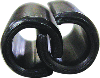
Figure 2
Example of interlocked Slotted Pins
- It allows pins to interlock (Figure 2), making feeding and installation difficult and time-consuming, which is always a major concern especially in high volume applications. This attribute does not allow for automatic feeding and installation of either style Slotted Pin.
- Usually, once installed in the recommended hole, the slot may close totally and the pin will become a solid part unable to absorb shocks and vibrations (Figure 3) imparted to the assembly during its life. Since the pin does not absorb the forces, the loads are transferred to the host sort material resulting in hole damage (enlargement) (Figure 5) and premature assembly failure.
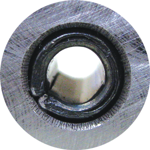
Figure 3
Installed Slotted Pin with a closed or "butted" slot
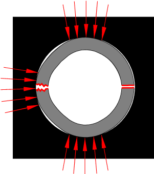
Figure 4
Non-Dynamic Condition: Installed Slotted Pin showing the “butted” condition making the pin unable to absorb dynamic loads
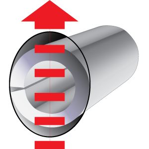
Figure 5
Direction of impact load and resulting hole elongation (enlargement)
- As the Slotted Pins are driven into the hole the slot will close creating a stress concentration line opposite the slot (Figure 6).
- During the manufacturing of Slotted Pins, material stresses are concentrated at 180º opposite the slot. When the pin flexes in the application, it flexes at the same location. The thinner material on the ISO 13337 light duty Slotted Pin is not able to easily absorb this additional material stress, and premature fatigue results in assembly failure.
- Shear strength will depend on pin orientation versus orientation of the applied loads. Slotted Pins need to be orientated to maximize strength.

Figure 6
Break Condition: Slotted Pin after fatigue failure at 180˚ from the gap
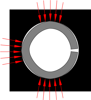
Figure 7
Normal Condition: Slotted Pin with three points of stress concentration in host
A Better Solution
All these problems can be avoided through the selection of the right spring pin. Coiled Spring Pins are a better solution. Coiled Pins can be easily identified by the 2-¼ coil cross-section.
The absence of a gap eliminates pin nesting and interlocking.
When Coiled Spring Pins are driven into the hole, the compression starts at the outer edge and moves through the coils towards the center. As a result, the joint will have equal stress distribution and uniform strength and flexibility, independent of the direction of the applied load (force).
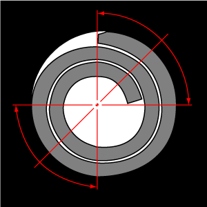
Figure 8
270º of contact with hole
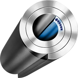
Figure 9
Installation flexibility
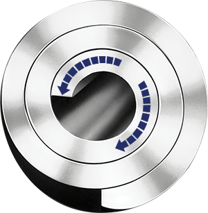
Figure 10
(CCW) Inward motion from compression.
(CW) Reverse motion when pressure is relieved
Since Coiled Spring Pins cannot butt, once installed they will be able to compress even further under additional forces, dampening shock and vibration that would otherwise be transmitted to the hole wall creating permanent damage. The Coiled Spring Pin becomes an active member of the assembly and prolongs the useful life of the end-product.
From the manufacturing point of view, Coiled Spring Pins are also a higher quality product. Coiled Spring Pins feature swaged chamfers at both ends (the bevelled chamfer of both types of ISO Slotted Pins is optional in one side for diameters > Ø10mm), and they are made to narrower diameter tolerances (270º of the circumference will be within the specified tolerance as opposed to an average of just three measures in the case of Slotted Pins). This results in more contact area between the pin and its host with a Coiled Spring Pin versus three points of contact on a Slotted Spring Pin. Square, clean-cut pin ends are also an important feature of Coiled Spring Pins.
SPIROL’s Standard Coiled Spring Pins are manufactured in three duties: heavy duty (ISO 8748), standard duty (ISO 8750) and light duty (ISO 8751).
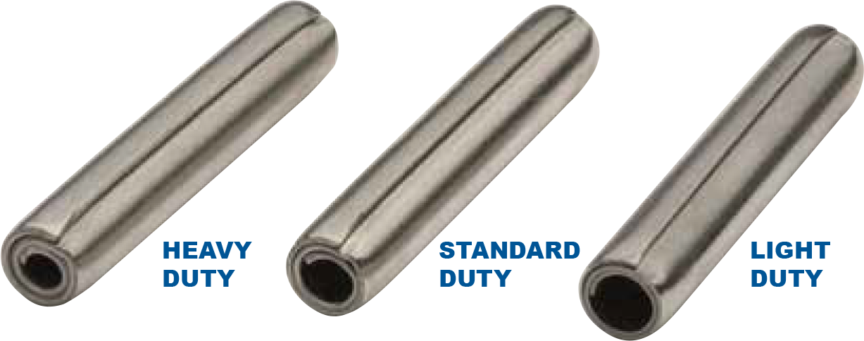
Light duty ISO 8751 Coiled Pins have been specifically designed for use in soft host material. The thinner material, and specifically designed coil relationships, deliver extra flexibility that will translate into reduced insertion forces, homogeneous axial forces and radial forces suitable for applications using soft materials. They will allow trouble-free automated installation, preventing damage to the hole. Ultimately, the selection of a light duty Coiled Pin for use in soft material hosts will protect the hole, reduce component cost preparation, increase productivity and enhance the overall quality of your end-product.
|
COMPARISON OF LIGHT DUTY SLOTTED SPRING PINS AND COILED SPRING PINS |
||
|
Light Duty Slotted Spring Pin |
Light Duty Coiled Spring Pin |
Benefits of Coiled Spring Pins |
|
Gap
|
No gap
|
No interlocking, equal stress distribution, uniform strength and flexibility, no need for orientation to maximize shear strength, trouble-free automation |
|
Horse-shoe shape |
270º contact with hole
|
Increase retention force, better transfer of dynamic loads |
|
Bevelled chamfer |
Swaged concentric chamfers in both ends
|
Easier installation, the smooth chamfer without sharp edges protects the hole |


 CHINA
CHINA Malaysia
  한국
한국  USA
USA  Canada
  United Kingdom
  Deutschland
  México
  Brasil
  Česká republika
  France
  España