
 CHINA
CHINA Malaysia
  한국
한국  USA
USA  Canada
  United Kingdom
  Deutschland
  México
  Brasil
  Česká republika
  France
  España
 The Pin
By
Download this WhitepaperAn attempt is made to analyze strain and stress of different types of pins in more detail than the conventional consideration of the shear strength offers. The analysis reveals that there are cases in which the shear strength is not the criterion for the proper selection of size and type of pin. It depends upon the mutual interaction of the pin and the parts to be joined due to the fit as well as due to the lateral load which can be purely statical of dynamical. The theoretical analysis – even if it consisted sometimes of rough approximations – of the effects of fit and of lateral load and the trend of experimental results show very clearly that a spirally coiled pin can be selected instead of any other type of pin of the same size. It offers advantages when static loads as well as when fluctuating loads are involved.
Stress And Strain Due To Interference Fit
A pin is a machine element that secures the position of two or more parts of a machine relative to each other. A large variety of types has been known for a long time; the most commonly used are solid cylindrical pins, solid tapered pins, groove pins, tubular slotted pins and spirally coiled pins.1 The choice of size and type of a pin for a given application must be based on a sound balance of stress and strain of the pin and of stress and strain of the parts to be joined. Stress and strain of both depend upon the magnitude of the interference fit between pin and hole and upon the forces to be transmitted from one part through the pin to the other part. These forces can be constant, intermittent of fluctuating.
The diameter D1 of the pin must be larger than the diameter D0 of the hole in order to obtain a press fit. When the pin is pressed into the hole by an axial force F, Fig. 1, the pin as well as the parts to be connected experience deformations which depend upon the difference D1-D0, upon the moduli of elasticity of the materials of the pin and of the parts to be joined and upon the shape of the pin and the parts.

Figure 1
Solid Pin
Solid Cylindrical Pin
In the case of a solid cylindrical pin joining two parts of fairly large size compared with the diameter of the pin hole, strain and stress can be easily calculated, at least so long as they are within the elastic range. The bearing pressure p at the surface of the pin hole follows from

where
E0 = Modulus of elasticity of material of joined parts
E1 = Modulus of elasticity of material pin
v = Poisson’s ratio
and the difference in Poisson’s ratios for different materials (0.3 for steel, 0.34 for aluminum) has been neglected. In the special case where E0 equals E1 , the bearing pressure is simply

The relationship between bearing pressure and stresses on the one side and the ratio (D1-D0 )/D0 on the other side is more complex in the case of the slotted tubular pin, Fig. 2, which apparently was first developed by Hans Hoffmann.2
The bearing pressure is not independent of the angular coordinate j if the thickness h is constant along the perimeter. Let

where p0 and pn are statically indeterminate quantities. They can be found by the condition that the pin can touch the surface of the hole but never penetrate it. By virtue of the constant term p0 on the right side of equation (3), the pin-hole diameter will increase uniformly, but the deformation of the pin is not rotationally symmetrical. It can be calculated by means of the theory of the initially bent beam; the radial component of the displacement is shown in Fig. 3 in multiples of (p0 r1 b3 )/(EI1), where r1 is half the diameter of the pin hole, b is the radius of the neutral fiber of the bent beam, and I1 is the moment of inertia per unit length (h3/12).
The difference between the shape of hole and pin as produced by a uniform pressure p0 can only be eliminated by the sum of the terms pn cos nj. The term p2 cos 2j, for instance, causes the hole to become slightly elliptical and the radial component of the displacement to have one more point of inflection when plotted versus the angular co-ordinate j. The deformation of the pin is closer to the deformation of the surface of the hole the more terms pn h cos nj are taken into account. From Fig. 3, it can be seen readily that the actual bending moment at the co-ordinate j = 0 is larger than the bending moment M0 by virtue of the constant term p0 alone at this point. If numerical values of the bearing pressure p0 and of the bending stresses in the pin are calculated for the commonly occurring relationship between pin and hole diameters, it will be found that the bearing pressure is well below any critical value for the parts to be joined, but that the maximum bending stresses in the vicinity of the co-ordinate j = 0 are far beyond the elastic limit of the material of the pin. This means that the whole calculation can only serve to show that plastic flow will result and where it will occur. This makes a more detailed investigation of the effects of the terms pn cos nj in the elastic range superfluous. In the entire range on both sides of the co-ordinate j = 0 where plastic flow occurs, the bending moment is lower than the one calculated with the initial assumption that the stresses would be entirely in the elastic range. Thus, it can be concluded that the bearing pressure will be still lower than the calculated one and that the danger of failure is shifted from the parts to be joined to the pin when a tubular slotted pin is pressed into the hole instead of a solid pin.

Figure 2
Slotted tubular pin

Figure 3
Deformation of slotted tubular pin
A= Elastic Line by Load p0
B= Circle
The Spirally Coiled Pin
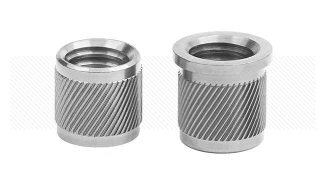
Fig. 4 shows a cross section of a spirally coiled pin. The shape of the cross section is close to the shape of the spiral of Archimedes. The departure from this shape is made (a) to minimize the area of surface along which there is no contact between hole and pin, and (b) to prevent the end -j0 of the outer coil of the pin from slipping in the peripheral direction over the adjacent coil.
An analysis of the bearing pressure between pin and hole and of the stresses in the pin and in the parts to be joined by virtue of the press fit again can be based on the theory of the initially bent beam. As the radius b of the neutral fiber is no longer constant, it is necessary to subdivide the pin into several portions of suitable width in the peripheral direction – say seven or more – and to assume that the radius b is constant within each portion, but changes abruptly at the transition from one portion to the adjacent one. As Fig. 4 shows, the change in curvature of the second coil is quite considerable in the vicinity of the end -j0 of the outer coil; thus, the portions must here be shorter than along the remainder of the coil.
The deformation of a spirally coiled pin due to the bearing pressure can generally be a displacement in the radial as well as peripheral direction. The displacement could be quite large in the peripheral direction if the cross section would be an exact Archimedean spiral; by the peculiar bulging out of the second coil, however, a peripheral displacement is almost completely prevented. Thus, the pin is much stiffer than without the bulge.
The calculation of stress and strain is quite lengthy since displacement and slope of the elastic line must be matched at each transition from one portion to the next one and since a statically indeterminate load in the tangential direction must be applied at the outer edge in order to account for the effect of the bulge.
The material of the pin experiences a plastic deformation during the manufacturing process. When the pin leaves the forming tool, the stresses due to this deformation are released instantly and the coils which have been pressed against the tool and each other during the forming operation open up so that a small gap appears between the coils; thus, the diameter of the unstrained pin is larger than the diameter during the manufacturing process. By proper selection of the size of the tool compared with the size of the hole, it is possible to keep the bearing pressure and the stresses in the coils within the elastic limit when the pin is put into the hole.
If a spirally coiled pin and a slotted tubular pin of equal nominal diameter are subjected to the same press fit ratio (D1-D0 )/D0 , the coiled pin is less stressed than the slotted pin provided that the cross sections of both pins have the same area normal to the axis of the pin. This can be demonstrated by a rigorous analysis; it also follows from the following comparison.
A laminated cantilever beam consisting of n layers of height h1 is deflected by the same amount (proportional to D1-D0 ) as a solid cantilever beam of the same overall height h2 = nh1 . Presume that length of the beam and width of the cross sections are the same, the ratio of the maximum bending stress s1 in each layer to the maximum bending stress s2 of the solid beam equals 1/n. This comparison is qualitatively admissible, but quantitatively, it is merely a first-order approximation since the radius of the neutral f iber of the curved beam is not precisely equal to (D1 – h1 )/2, but smaller by the factor [1 – h1 2/3(D1 – h1 )2] and since the inner coil has a still smaller radius than the outer coil.
From this comparison, it also can be concluded that the power required for forming a pin decreases with decreasing thickness of the strip. This offers the possibility of manufacturing spirally coiled pins with diameters beyond the conventional range; i.e., larger than 1/2 inch provided that there is a demand for them.

Figure 4
Coiled rolled or SPIROL wrapped pin
Stress and Strain Due to External Load
The Solid Pin
Fig. 5 shows two slabs A and B of thickness hA and hB, respectively, being joined by a pin. A force P is applied at each slab; for establishing equilibrium of the whole system, moments M must also be applied of magnitude (hA + hB )P/2.
The slabs are assumed for a moment to be infinitely large in any direction perpendicular to the axis of the pin. It is quite obvious that any load applied at the cylindrical surface of the hole has little effect at any point far distant M hB P Fig. 5 External load of a pin. from the axis. Thus, it is justified to consider the remote portions of the slab as being absolutely rigid and only the portions within a cylinder of radius, re as elastically f lexible. If the elastic portion is replaced by a system of radial springs, a model is obtained which can be used for studying the interaction of pin and slabs and which can be made equivalent to the actual system by a suitable choice of the radius re and the stiffness of the springs.
The pair of action and reaction forces P creates a displacement y of slab A relative to slab B by virtue of the elasticity of the springs. If the pin is assumed to be absolutely rigid, it turns into a position as shown in Fig. 6. If the pin is elastically flexible, it does not only turn, but it is also bent as shown in Fig. 7. Obviously, the deformation is more concentrated at the immediate vicinity of the surface of contact between slabs A and B the weaker the pin is compared with the springs.

Figure 5
External load of a pin

Figure 6
Stiff pin

Figure 7
Flexible pin
Strain and stress of the pin can be calculated by means of the theory of the beam on an elastic foundation. For these calculations, the parameter of the foundation elasticity – sometimes called the bedding coefficient – needs to be known. It might be difficult to obtain this information by theoretical considerations, but it is always possible to deduce it from experiments.
It can be seen easily that the bedding coefficient depends upon the modulus of elasticity of the material of the parts A and B. This means that a steel pin in a steel structure will behave differently from a steel pin in a cast iron or aluminum structure.

Figure 8
Symmetrical arrangement of a double shear pin

Figure 9
Ratio tmax / smax versus m/D
Fig. 8 shows an arrangement symmetrical with respect to the geometrical configuration and to the loading. A double shear jig having such a symmetrical arrangement is recommended for testing pins. The theory of the beam on an elastic foundation leads to the following results regarding the shear stresses t and the bending stress sa . The maximum shear stresses tmax occur in the plane of contact of parts A and B or A1 and B, respectively, the maximum bending stresses sa max occur in the center plane of part B up to a certain ratio of m/D (where 2m is the thickness of part B and D as previously the diameter of the pin). The tmax /sa max depends also upon the ratio of m/D and, naturally, upon the bedding coefficient; it is represented in Fig. 9 for a bedding coefficient which has been deduced from experiments. If shear strength and tensile strength of the material of the pin is known, it can be predicted whether an eventual failure will be caused by shear or by bending stresses. For this conclusion, the normal stresses by virtue of the press fit must be taken into account; note that the stresses due to the fit are radial and tangential while the bending stresses due to the external forces P are axial. Thus, the state of stress in the pin is triaxial.
If the pin breaks by normal stresses, the fracture occurs inside one of the parts. Such fractures have been observed.
The Slotted Tubular Pin
The positioning of the slot of a slotted tubular pin in relation to the applied force is significant. Two limiting positions are possible, mainly one where the slot is 90˚ from the direction of the forces P1 and P2 , Fig. 10, and the other where the slot is in line with the direction of the forces P1 and P2 – see Fig. 11. Couples P1 ’P1 ” and P2 ’P2 ” must be added in order to establish equilibrium with the external moment M, Fig. 5. The fundamental difference between both arrangements as shown in Figs. 10 and 11 consists in the position of the forces P1 and P2 relative to the shear center of the slotted pin. The shear center is at the symmetry axis of the cross section opposite to the slot as shown in Figs. 10 and 11. Let rm be the mean radius of the slotted tubular pin, i.e., be equal to 1/2(D1-h), Fig. 2 or Fig. 10, and let ±j0 be the angular co-ordinates of the edges of the slot. With the assumption that the thickness h is small compared with the mean radius rm , the distance zs of the shear center from the center of the circle of radius rm follows from


Figure 10
Slot 90˚ from direction of load
A= Shear Center

Figure 11
Slot in line with direction of load
A= Shear Center
For j0 <p/2, formula (4) can be replaced by the approximation
![]()
For the special values j0 = p/2 (half cylinder) and j0 = p (infinitesimal slot), the distance zs = (4/p)rm and zs = 2rm , respectively. The ratio zs /rm are plotted versus the angle j0 in Fig. 12.
If the lines of action of the resultants P1 and P2 go through the shear center of the cross section, the deformation of the pin is a pure bending deformation. If, however, the lines of action of P1 and P2 have a distance zs from the shear center, there is also a torque proportional to zs and a distortion in addition to the bending, moreover, bending stresses are locally higher than in the case zs = 0. Thus, the pin in the arrangement-slot 90˚ from the direction of the forces is weaker than the same pin in the other arrangement-slot in line with direction of the forces. This conclusion is in agreement with the statement of Leo F. Spector3 that the difference in shear strength is about 6%.
It is quite obvious that stresses sa parallel to the axis of the pin due to a bending deformation in the direction y cannot be very large in a multiple shear pin as shown in Fig. 13 when the thickness h of the slabs to be joined is small compared with the diameter of the pin. Such an arrangement again, reveals that the magnitude of the maximum force which can be applied to the joint depends upon the location of the slot relative to the direction of the force. This can be shown as follows.
The lateral force P creates a pressure q at the surface of the hole which is a function of the abscissa x and of the angular co-ordinate j. The force qR dj dx acting at the area element Rd dx has a component parallel to the lateral force P of magnitude qR sinj dj dx.
If there are n contact areas between the slabs, the axial length of the surface of the hole is (n+1)h. In case I – slot 90° from the direction of force P – the integral f the components qR sinj dj dx from j = 0 to j = j0 and from x = 0 to x = (n+1)h must be equal to the force P. Thus

If q is equated to q0 FI where q0 is assumed to be independent of the abscissa x as a first-order approximation and FI is a function of the angular co-ordinate j, it follows that

The component qR sinj dj dx has a moment arm b(1 – cosj) with respect to an axis through the point r = b, j = 0 where b denotes the radius of the neutral fibre as in section (B-2). Thus, it exerts a moment dMtI about this axis. By integrating, it follows that the bending moment MtI is

or with the previous assumption and with respect to Equation (7)


Figure 12
Shear center position
j1= Position of the center of the shear

Figure 13
Multiple shear pin
n= number of contact surfaces
Left: Case I
Right: Case II
In case II – slot in line with the direction of force P – the bending moment at r = b, j = 0 is

With the simplifying assumptions j0 = p, j1 = p/2 and FI = FII equating unity, it follows that
![]()
It is quite difficult to find a reliable estimate of the functions FI and FII for the following reason. It has been shown in the section, “Slotted Tubular Pin,” that the stresses stp in the pin by virtue of the press fit are in some portions of the cross section equal to the yield strength and in other portions still in the elastic range. The stresses stI or stII due to the moments MtI or MtII should be added to the stresses stp. This is impossible in the portions where plastic f low already occurred when the pin was pressed into the hole unless strain-hardening took place. Because of the complexity of the actual conditions, only the generalized statement can be made MtII is smaller than MtI for the same external load P.
The previous statement that the slotted pin in the arrangement: slot 90° from the direction of the force is weaker than in the arrangement: slot in line with direction of force holds also for the multiple shear pin.
The Spirally Coiled Pin
The position of the shear center of the cross section as shown in Fig. 4 could be calculated from formula (4) if the thickness h of the strip would be very small compared with the radius of the neutral fibre and if both ends – at the angular co-ordinate –j0 as well as at +j0 – would be free ends. The first condition would mean that the difference between the mean radius of the outer coil and the mean radius of the inner coil is negligibly small. The second condition is satisfied at the inner end +j0 of the strip but not at all at the end -j0 of the outer coil. This end experiences a strong support by the bulge as mentioned already in the section, “Spirally Coiled Pin” so that the outer coil acts almost like a tubular cross section without a slot.
Thus, the shear center must be close to the center of the hole. This conclusion is confirmed by experiments which show no noticeable effect of the positioning of the ends of the strip in the pin hole on the shear strength.
The moments of inertia about different axes j are slightly different. Since the effective diameter of a coiled pin can never become smaller than the nominal diameter by virtue of the bulge, the moments of inertia are just slightly smaller than that of a solid pin of the same nominal diameter. Thus, the selection of the proper size of a spirally coiled pin can be based on the same deliberations as the case of a solid pin.
Objections might be raised against the application of the same size for spirally coiled and solid pin when shear stresses alone are considered. If the shear stresses constitute the criterion according to Fig. 9 for the proper size of the pin, the “heavy-duty” type (there are also “medium” and “light” coiled pins available) with a cross section of approximately 75% of that of a solid pin of the same nominal diameter is to be used. If both pins would be made of the same material, it could be expected that the static shear strength of a spirally coiled pin will be lower than that of a solid pin. Tests, however, made in accordance with specifications of several government agencies show a slightly higher static strength of the coiled pin.
This observation can be explained partly by the fact that solid pins are much more prestressed by the bearing pressure (Section Stress and Strain Due to Interference Fit), partly by the magnitude of the ultimate strength of different materials after different heat-treatment and partly by the metallurgical phenomenon that the ultimate strength of a material is found to increase for decreasing thickness of the test specimen. If, for instance, the ultimate strength of a sheet of 0.016-in. thickness is taken as unity for a comparison, the ultimate strength of sheets of different thickness can be taken from Table 1.
| Thickness, in. | Ratio of Ultimate Strength |
| 0.002 | 1.213 |
| 0.008 | 1.100 |
| 0.012 | 1.042 |
| 0.016 | 1 |
| 0.020 | 0.965 |
| 0.024 | 0.940 |
Table 1
The performance of any pin under dynamical load, may it be intermittent or oscillating, is difficult to predict by theoretical considerations only since there are so many effects involved as, for instance, fatigue strength of the material the pins are made of, damping of the vibrations by virtue of friction which depends upon the interference fit of pin and hole or between the parts to be joined and so forth.
Thus, it must be relied upon experiments which give the better information for a special application the closer the conditions of the actual application are simulated in the tests. Such tests have been performed4 with a frequency of 2000 load cycles per min. In order to obtain fractures in a reasonable time, the magnitude of the fluctuating load has been selected alternating between plus and minus half the ultimate static load. Under these very severe conditions, the spirally coiled pins lasted much longer than solid or slotted tubular pins; the fracture occurred in the outer coil only.
The times recorded for a large number of tests on spirally coiled pins scattered by approximately 10 percent. The scattering of the results of the other type pins was also larger.
Scattering of test results is inevitable if test specimens are picked at random out of the production line. It is primarily caused by the tolerances of the pin diameter. If it is assumed that the hole is thrilled with exactly the nominal diameter D0 and that departures from the nominal diameter D1 of the pin occur within the standard tolerances ±e, the ratio (D1 ±e – D0 )/D0 being responsible for the bearing pressure and for the stresses due to the pressfit may vary considerably since D1 – D0 itself is a small quantity. The differences in scattering seem to indicate that the different types of pins are differently susceptible to standard tolerances.