
 CHINA
CHINA Malaysia
  한국
한국  USA
USA  Canada
  United Kingdom
  Deutschland
  México
  Brasil
  Česká republika
  France
  España
 How to Select a Threaded Insert for Your 3D Printed Assembly
By
Download this WhitepaperLike injected molded plastic assemblies, Threaded Inserts are commonly used in 3D printed assemblies to provide reusable threads and enhance joint strength. This White Paper provides recommendations, design guidelines, and performance expectations for various Threaded Inserts used in Fused Deposition Modeling (FDM), Selective Laser Sintering (SLS), and Stereolithography (SLA) 3D printing processes, which are the most relevant additive manufacturing technologies for assemblies that benefit from the performance enhancements afforded by Threaded Inserts.
3D Printing Overview

Figure 1 SPIROL Series 29 Long Heat/Ultrasonic Insert in a 3D printed yo-yo assembly
Material Extrusion - Fused Deposition Modeling

Figure 2 FDM Printer Technology
Powder Bed Fusion - Selective Laser Sintering

Figure 3 SLS Printer Technology
VAT Photopolymerization - Stereolithography

Figure 4 SLA Printer Technology
FDM printing involves extruding melted thermoplastic filaments through a heated nozzle and building parts layer by layer. It is the most widely used 3D printing method due to its affordability and user-friendliness. Common materials for FDM include PLA, ABS, and PETG.
SLS printing uses a laser to fuse layers of powdered thermoplastics. This method is ideal for creating complex geometries and yields parts with excellent mechanical strength. The most common material in SLS is Nylon.
SLA printing uses a UV laser to cure liquid thermosetting resins layer by layer through photopolymerization. This process produces parts with high resolution and accuracy.
Threaded Insert Recommendations
Threaded Inserts come in various types, often categorized by their installation method, such as post-mold heat/ultrasonic-install and cold press-in. The optimal Insert type for a 3D printed application is determined by the host plastic material.
For Thermoplastics (FDM and SLS)
Thermoplastics can be heated and cooled multiple times with minimal change to their properties. Therefore, Threaded Inserts can be installed into thermoplastic 3D printed assemblies using heat (thermal) or ultrasonics, or they can be simply pressed into or threaded into the assembly:
- Heat/Ultrasonic Inserts: Recommended for assemblies requiring the highest tensile and torque performance.
- Press-In Inserts: Deliver moderate tensile and torque performance, and are the simplest to install as they do not require specialized equipment.

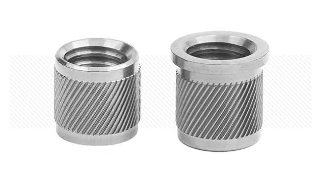
Figure 5 SPIROL Series 19/20 (top) and Series 29/30 (bottom) Heat/Ultrasonic Inserts
For Thermosetting Plastics (SLA)
Thermosetting plastics remain permanently solid after curing and decompose rather than melt when subjected to high temperatures. Therefore, it is advisable to install Threaded Inserts in a “cold” condition:
- Press-In Inserts: The most effective choice for thermosets.
- Self-Tapping Inserts: A viable alternative that may require less force to install, but limits back-out torque performance.
- Expansion Style Inserts: Most simple to install, however, performance is the least of all Insert styles.

Figure 6 SPIROL Series 50 (top left) and 51 (top right) Press-In Inserts and SPIROL Series 10 Self-Tapping Insert (bottom)
Material Properties
Insert performance is strongly influenced by the properties of the host material.
- Tensile Strength: Measures the material’s property to resist plastic deformation
- Flexural Modulus: Influences material stiffness and ability to distribute bending forces, critical in preventing deformation and ensuring proper load distribution
Additionally, thermal properties will affect the installation process, as higher conductivity materials promote more uniform heat distribution, improving plastic flow and ensuring complete fill around the retaining features for a secure bond. Likewise, the heat deflection temperature for a given plastic will influence the temperature for heat or ultrasonic installation of the Threaded Insert.
Design Guidelines
The performance of a Threaded Insert in 3D printed materials is influenced by several key factors. This section outlines essential design guidelines, focusing on host hole size, material properties, wall thickness, infill, and layer thickness to ensure optimal performance of the Threaded Insert in 3D printing applications.
Hole Size
Hole size is critical for the performance of Threaded Inserts. SPIROL’s Threaded Insert Catalog provides guidelines for hole size, but 3D printing tolerances often exceed the recommended +0.08mm. Typical tolerances are as follows:
- Industrial FDM printing: ±0.2mm
- Desktop printers: ±0.3-0.5mm
- SLA printers: ±0.1mm
- SLS printing: ±0.3mm
To mitigate variation, one option is to drill holes in the plastic host, which reduces variation but may compromise reinforcement in FDM-printed outer walls (discussed further in this White Paper). Alternatively, iterative development can be done until the optimal hole size is achieved.
Wall Thickness
Threaded Inserts require sufficient solid wall thickness in the surrounding area to meet performance expectations. For optimal Insert performance, design the number of outer wall loops to create a solid feature (boss) of at least 1.5 times the Insert’s knurl diameter. For an M6 Threaded Insert, this occurs at 6 wall loops (@0.4 mm nozzle diameter). Maximum performance potential is reached with a boss of at least 2 times the Insert knurl diameter.

Figure 7 15% Infill with 2 wall loops (left), 55% Infill with 5 wall loops (right)

Figure 8 Insert performance as a function of wall loops (PLA material, 15% infill, testing performed with SPIROL INS 29 M6 short)

Figure 9 Insert performance as a function of infill (PLA material, 2 wall loops, testing performed with SPIROL INS 29 M6 short)
Infill (FDM only)
Insert performance increases linearly with infill density. For optimal Insert performance, design with an infill density of greater than 50%.
Layer Thickness (FDM, SLS)
In general, thicker layers result in weaker inter-layer bonding as there are larger voids. Best Insert performance typically occurs around 0.16-0.2 mm layer thickness for FDM and SLS, where tensile strength is optimized.
Insert Performance Comparison
Let’s compare the performance of three (3) different series of M6 Threaded Inserts; Symmetrical (SPIROL INS 29 Long) and asymmetrical (SPIROL INS 19 Long) heat-installed, and a Press-In Threaded Insert (SPIROL INS 50) in common 3D printing materials. Detailed comparative test results are provided for FDM, SLS, and SLA printed components. These insights will help designers choose the optimal Threaded Insert based on specific performance requirements.
FDM Printed Components
As expected, the performance of the Heat-Installed Threaded Inserts exceeds that of the Press-In Inserts in the various 3D printed materials. This is consistent with performance in extruded plastics.

Figure 10 FDM Tensile Performance Measurement Averages, M6, Newton Meters (Nm)*
SLS Printed Components
Despite SLS components being manufactured at 100% infill and potentially achieving mechanical strength comparable to molded or extruded components, microporosity can significantly reduce Insert performance.

Figure 11 SLS Tensile Performance Measurement Averages, M6, Newton Meters (Nm)*
*Testing of FDM samples was performed at 55% infill and 1.5x wall thickness (5 wall loops). Estimated values for Insert performance may be calculated based off the infill – performance relationship. Layer thickness was maintained at 0.16mm to maximize tensile strength as it facilitates fine material deposition. Raster angle was maintained at ∠0°.
SLA Printed Components
Given that SLA printing materials are primarily thermosetting plastics, only Press-In Inserts can be used effectively as they are ideally suited for press-in installation without heating the host material.
Self-Tapping Threaded Inserts are a viable alternative, but as they are threaded into the assembly, their assembly is time-consuming and may thread out of the assembly if the assembly is non-permanent. Because of this difficulty, Self-Tapping Threaded Inserts were not included in this study; as well as Expansion-style inserts due to their low performance.
| Material | Torque (N*m) | Tension (N) |
|---|---|---|
| Resin | 7 | 40 |
Table 1
SPIROL’s Press-In Insert (INS 50 / M6 / .312 EK) performance in clear photopolymer resin
Comparison to Molded Components
When comparing the differences between the components manufactured in molded plastic and 3D printing methods, it is important to note that the same material may have widely varying properties affecting the Insert’s performance.
Despite the layered geometry of FDM printed components, they reach high performance – especially when using Heat/Ultrasonic Inserts. A direct comparison of FDM printed polycarbonate (PC) and extruded plastic is shown in Figure 12.
SLS prints are more prone to microcracking and early failure of the Insert. SLS powders tend to exhibit weaker material properties than similar plastics for molding, often due to differing compositions and microporosity in the final printed components. Since the material properties differ to a high degree, an Insert performance may be anywhere from 20% to 50% less than in an extruded plastic.

Figure 12 Performance Comparison for FDM and Extruded/Molded plastics (FDM: 55% infill and 5 wall loops)

Figure 13 Soldering iron
Installation Methods for Prototyping
As much as 70% of an Insert’s performance is a direct result of the quality of installation- especially when it comes to heat or ultrasonic installation. Alignment, temperature, pressure, and weld time are all important factors.
Best results in prototyping laboratories are achieved using purpose-built equipment.
For quick trials or where specialized equipment is unavailable, a soldering iron may also be used. It should be noted that when using a soldering iron for Insert installation, it is preferable that it is equipped with a tip that engages the Insert as much as possible. A good operating temperature for installation with a soldering iron is typically between 650°-750°F (343°-399° C) A rule of thumb to gage the installation temperature by direct heat is to add an additional safety factor to the heat deflection temperature for the given material:
Tinstall = T heat deflection + 150°F (65°C)
The heat deflection temperature is the temperature at which a thermoplastic deforms under a specified load. Apply constant pressure to the insert by pushing down the soldering iron as it contacts the Threaded Insert.
For Press-In Inserts, an arbor press should be used to apply constant pressure; in softer plastics, a hammer may be a low-cost installation option.
For low to high volume production solutions, consider semi-automatic or fully automatic installation equipment.
Key Takeaways
Heat/Ultrasonic Inserts provide the highest strength in 3D printed thermoplastics, while Press-In Inserts serve as a viable alternative, particularly for thermoset materials, where heat installation is not feasible. Thermoset plastics inherently limit Insert options to press-in methods.
Key findings indicate that Threaded Insert performance improves with increased infill density and wall loops in FDM printing, with optimal results at a layer thickness of 0.16-0.2 mm, 50% or more infill, and number of wall loops equal to or higher than the nominal metric Insert size.
Results show that at high infill and wall thickness, FDM 3D printed components carry approximately 70-80% of the performance in an equivalent molded material. While SLS components exhibit high theoretical strength, their microporosity can carry approximately 50-70% of the performance compared to molded plastics.
Contact SPIROL for assistance in choosing the right Threaded Insert for your 3D printed production and prototype designs. Due to the variety of 3D printing methods, materials and parameters, results may vary and thorough testing and evaluation for individual assemblies is recommended.